
Installation for separating components in a plurality of parallel channels

a technology of components and parallel channels, applied in the direction of separation processes, instruments, process and machine control, etc., can solve the problems of complex and difficult implementation of components separated complex collection and discarding of components in the various different channels, and known devices with the drawback of being complex and very expensive, etc., to achieve simple, effective and inexpensive

Inactive Publication Date: 2005-10-13
BIONISIS SA
View PDF12 Cites 2 Cited by
  • Summary
  • Abstract
  • Description
  • Claims
  • Application Information

AI Technical Summary

Benefits of technology

[0010] A particular object of the present invention is to provide a solution to this problem that is simple, effective, and inexpensive.
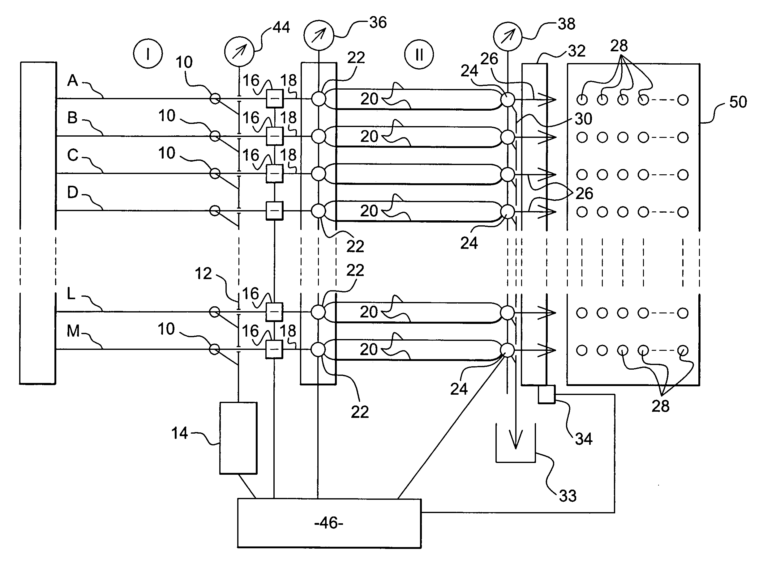
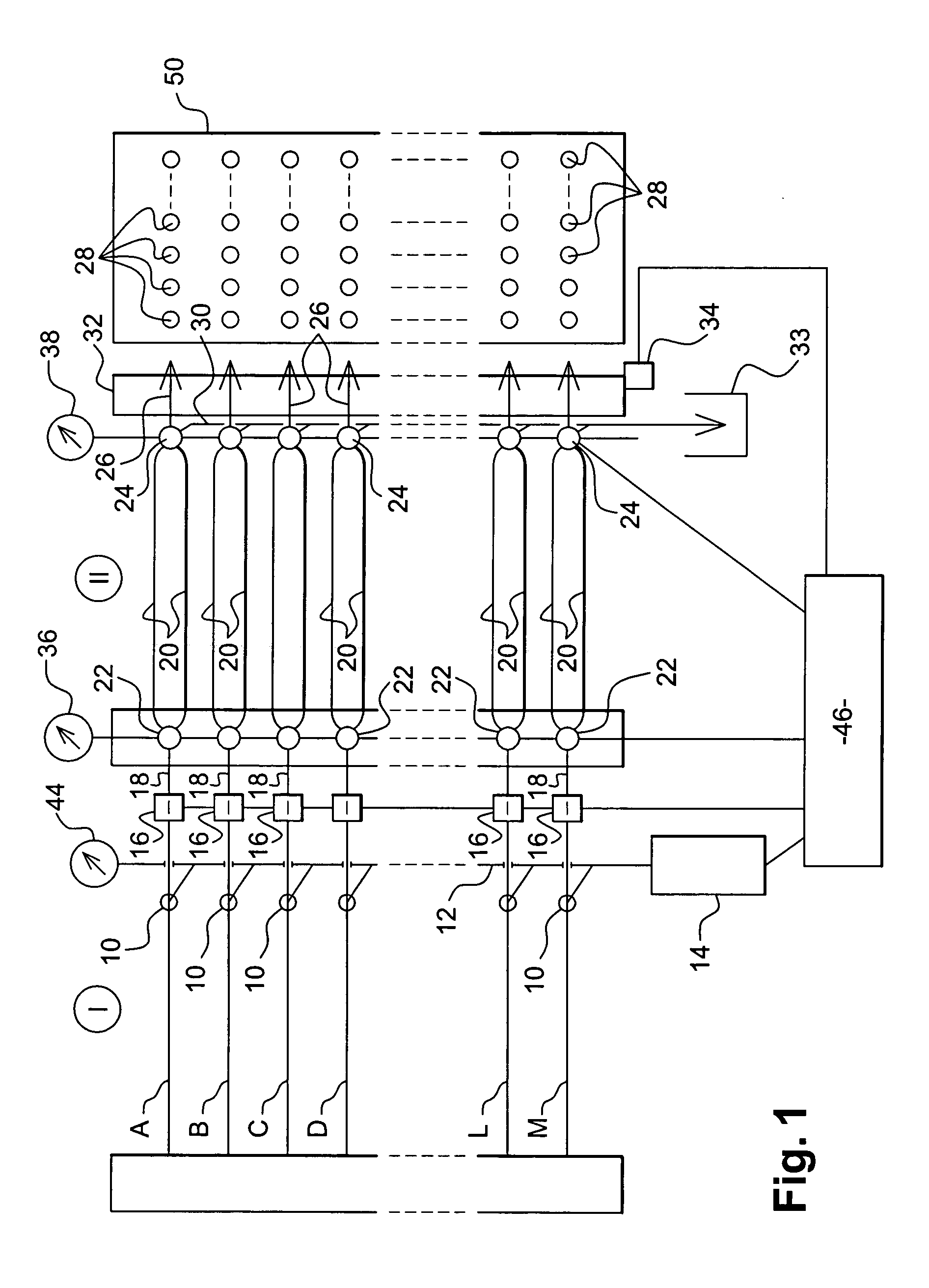
[0011] The invention provides an installation for separating components, in particular by high-pressure liquid chromatography in a plurality of parallel channels, the installation making it possible, at will, to select from amongst the components separated in the various channels, those components that are to be conserved and those that are to be discarded, and to collect with precision the components that are to be conserved without any risk of said components remixing at the time they are collected.
[0013] The parallel temporary storage means that are connected to the outlet of each separation channel serve to transform the continuous flows leaving the separation channels into discontinuous selective distribution of the separated components either to collector means or to disposal means, thereby facilitating and greatly simplifying the collection of separated components.
[0015] The temporary storage means can be emptied much more quickly than they are filled, thus making it possible to have plenty of time for preparing to distribute the separated components to the corresponding collector means or to the disposal means.

Problems solved by technology

The selection, collection, and discarding of components separated in the various different channels thus very quickly become complex and difficult to implement, once the number of separation channels in parallel increases.
Nevertheless, that known device has the drawback of being complex and very expensive and it does not make it possible to avoid the above-mentioned drawbacks associated with the difficulty of collecting separated components leaving a plurality of parallel separation channels.

Method used


Image

  • Installation for separating components in a plurality of parallel channels
  • Installation for separating components in a plurality of parallel channels
  • Installation for separating components in a plurality of parallel channels

Examples


Embodiment Construction

[0032] The installation of the invention which is shown diagrammatically in FIG. 1 comprises a first portion I which is an installation for separating the components of samples by high-pressure liquid chromatography, of the type commonly referred to by the initials HPLC or OPLC (over-pressure liquid chromatography), and a second portion II which is connected to the outlet from the first portion I for the purpose of temporarily storing the separated components leaving the separation channels of the first portion I, and for distributing them selectively to collector means or to disposal means or means for discharging waste to the sewer.

[0033] The first portion I comprises a plurality of separation channels A, B, C, D, . . . , L, M in parallel having their inputs fed with eluants, and each receiving a sample of a substance that is to have its various components separated, in particular for the purpose of characterizing their biological activities and their identities.

[0034] Each sepa...


PUM

PropertyMeasurementUnit
Pressureaaaaaaaaaa
Volumeaaaaaaaaaa
Molecular weightaaaaaaaaaa

Abstract

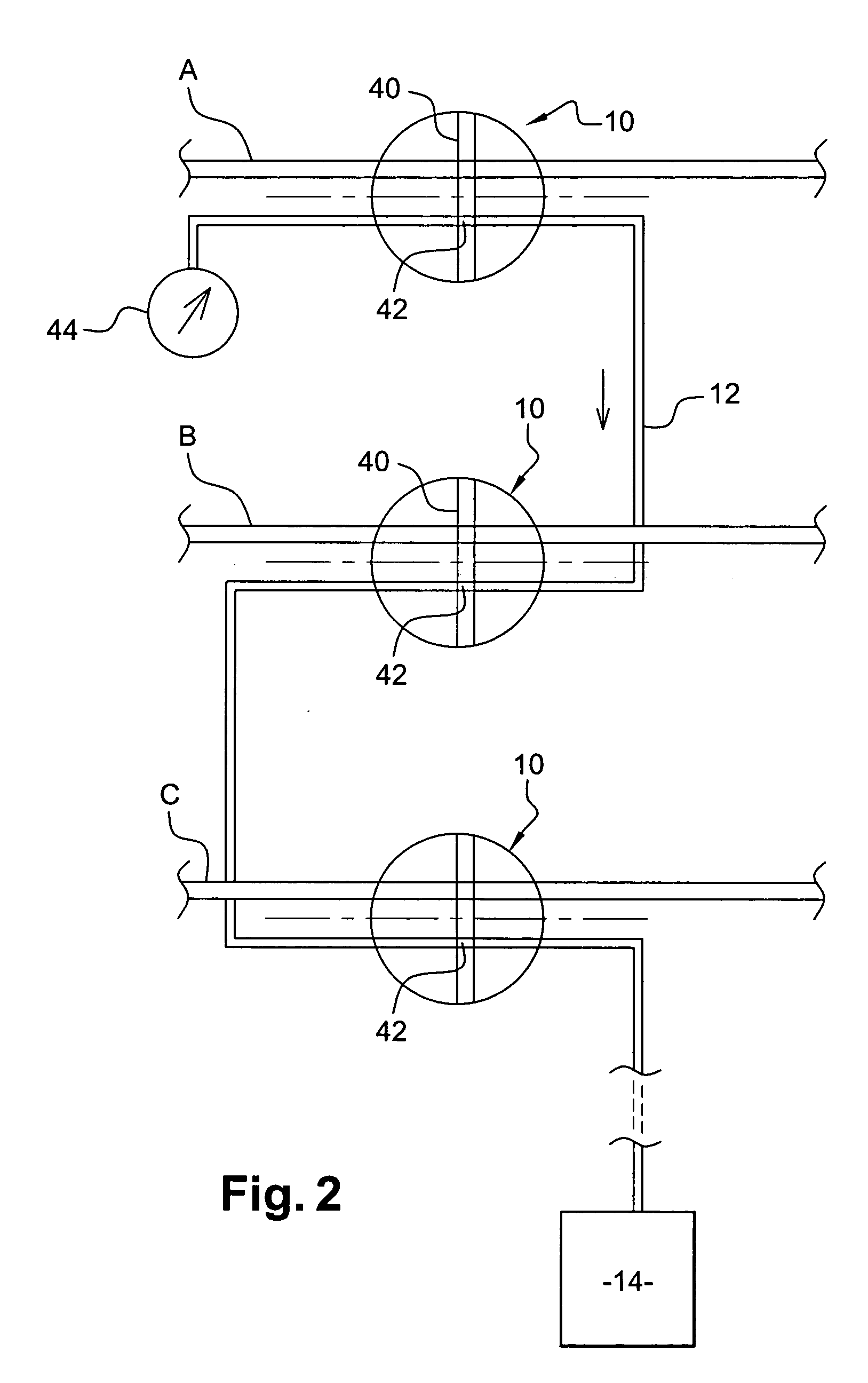
An installation for separating components, in particular by high-pressure liquid chromatography along a plurality of channels in parallel, the outlets from the channels being connected via controlled selective connection means to the inlets of parallel temporary storage means whose outlets are connected via controlled selective connection means to ducts for depositing in collector means or in disposal means.

Description

[0001] The invention relates to an installation for separating components in a plurality of parallel channels, in particular by high-pressure liquid chromatography, capillary electrophoresis, or any other technique for separating components in ducts. [0002] Such a separation installation makes it possible in particular to purify a given component or to extract the components from a mixture. BACKGROUND OF THE INVENTION [0003] The development of high-throughput means for synthesizing chemical molecules, the development of techniques for parallel synthesis, and the growth in studies on biodiversity and on medicinal plants has led to ever-increasing needs in terms of molecule purification. [0004] Separation systems operating by high-pressure liquid chromatography in parallel channels satisfy this requirement. The separate components in the various channels are collected by means of suitable receptacles placed at the outlet of each channel, and by means of moving arms each carrying the o...

Claims


Application Information

Patent Timeline
IPC IPC(8): G01N1/00G01N27/62G01N27/447G01N30/26G01N30/32G01N30/46G01N30/72G01N30/74G01N30/78G01N30/80G01N30/82G01N30/84G01N30/86G01N37/00
CPCG01N30/467G01N30/82G01N30/84G01N2030/8417
Inventor KERHUEL, MARTINMANACH, MICHEL
Owner BIONISIS SA
Learn More