
Leak resistant lid assembly for a beverage container

a beverage container and lid technology, applied in the field of leak-resistant lids for containers or cups, can solve the problems of affecting the leakage rate of liquids, the tendency of liquids to leak out of the lid in the rim area, and the approach is not entirely successful, so as to achieve the effect of high leakage resistan

Inactive Publication Date: 2005-10-13
INT PAPER CO
View PDF26 Cites 61 Cited by
  • Summary
  • Abstract
  • Description
  • Claims
  • Application Information

AI Technical Summary

Benefits of technology

The present invention provides a leak-proof lid for paper beverage cups that effectively prevents liquid from leaking between the cup and lid when the cup is inclined for drinking. This is particularly important for consumers who purchase drinks in cups with lids applied. The lid is designed to be placed over a thick seam on the cup, which can often result in leakage. The lid has a mounting ring that seals with the cup, a skirt that extends over the cup's outer wall, a flange that extends radially inward, and an upstanding wall that forms a closed lid structure with a drinking orifice. The mounting ring is complementary to the cup, ensuring a tight seal and preventing leakage. The technical effect of this invention is to provide a reliable and leak-proof lid for paper beverage cups, which meets consumer expectations and prevents leakage between the cup and lid.

Problems solved by technology

However, many designs fall short of this important objective.
A particular problem arises in connection with some containers which are formed such that each of their side wall and rim are formed into a closed vessel by overlapping the material (relatively thick paper) at a joint or seam.
When a lid having a spout or orifice for drinking is placed over such a thick seam, there is a tendency for leakage out of the lid in that area of the rim.
This approach is not entirely successful since many users do not receive, understand or remember this instruction.

Method used


Image

  • Leak resistant lid assembly for a beverage container
  • Leak resistant lid assembly for a beverage container
  • Leak resistant lid assembly for a beverage container

Examples


Embodiment Construction

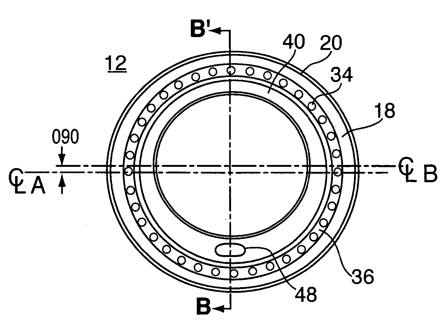
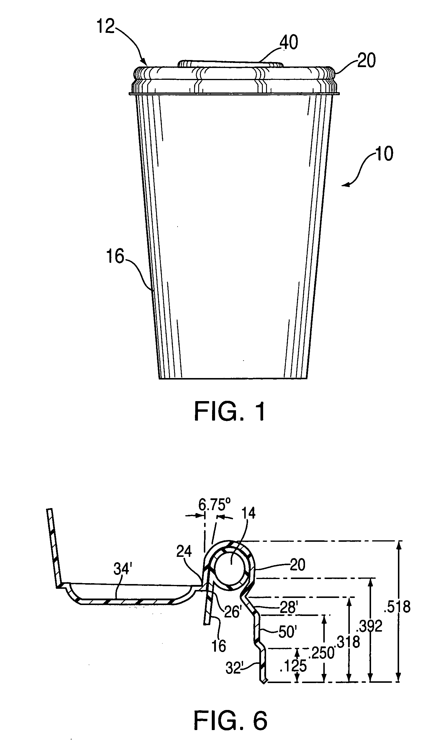
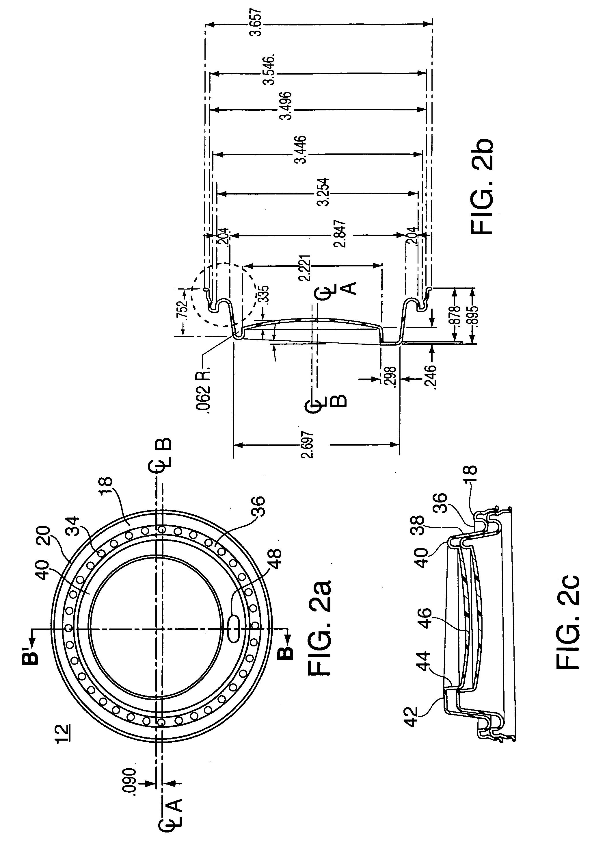
[0018] Referring to FIG. 1, a typical container or cup assembly 10 suitable for beverages and being formed from paper, plastic, plastic foam or the like, in a generally cylindrical or frusto-conical shape, is shown. A lid 12 constructed according to the present invention is shown sealably mounted at the top of container 10. Lid 12 (other forms of which are shown in greater detail in others of the figures) preferably is produced by thermoforming a thin, flat sheet of clear or opaque (black, white or colored) plastic such as polystyrene onto a lid mold to form the desired lid shape which will be explained below. The lid may also be formed by injection molding while maintaining the desired properties and characteristics as set forth hereinafter. The thickness of the plastic for the lid typically is about 0. 017 inches in its finished form.

[0019] The container 10 typically is a paper cup suitable for hot or cold beverages and will be referred to hereinafter as cup 10. As is customary, ...


PUM

PropertyMeasurementUnit
diameteraaaaaaaaaa
diameteraaaaaaaaaa
diameteraaaaaaaaaa

Abstract

A leak resistant lid for a beverage container is formed with a depending skirt portion having one or more progressively decreasing diameter rings between a lower extremity and a sealing channel adapted to fit over the rim bead of the container. An inner wall of the channel extends downwardly inside the inner surface of the side wall of the container in a plug fit relationship. The relatively deep inside plug fit provides added surface area contact for sealing the interface between the lid and the container. An elevated and rigid central plateau supports a drinking orifice and is connected to the inner wall of the channel by a reinforced, rigid flange or web which maintains the channel and its inner wall in leak resistant relationship with the rim bead and container wall.

Description

CROSS-REFERENCE TO RELATED APPLICATIONS [0001] Not Applicable STATEMENT REGARDING FEDERALLY SPONSORED RESEARCH OR DEVELOPMENT [0002] Not Applicable FIELD OF THE INVENTION [0003] This invention relates to containers for liquids, to lids for such containers and, more specifically, to replaceable, leak resistant lids for containers or cups having a generally cylindrical or frusto-conical shape. [0004] Although the invention described herein is particularly suitable for application to beverage drinking cups, a person skilled in this art readily may apply the invention to other similar containers which require a removable, leak resistant lid. SUMMARY OF THE INVENTION [0005] In accordance with the present invention, a highly leak resistant “sipper” lid suitable for paper beverage cups is provided. The unintentional passage of liquid between the mating surfaces of a cup and a lid is effectively suppressed. This feature meets consumer expectations in that, when consumers purchase drinks in ...

Claims


Application Information

Patent Timeline
Patent Type & Authority Applications(United States)
IPC IPC(8): A47G19/22B65D41/18B65D43/02
CPCB65D43/0208B65D2543/00046B65D2543/00092B65D2543/00296B65D2543/00518B65D2543/00537B65D2543/00564B65D2543/00638B65D2543/00731
Inventor BROWN, WILLIAM L.CROWELL, TIMOTHY E.HAASE, SARAH M.
Owner INT PAPER CO
Learn More