

Support structure of parts for vehicle
- Summary
- Abstract
- Description
- Claims
- Application Information
AI Technical Summary
Benefits of technology
Problems solved by technology
Method used
Image

Examples
Embodiment Construction
[0015] An embodiment of the present invention will be explained below with reference to the drawings, wherein like members are designated by like reference characters.
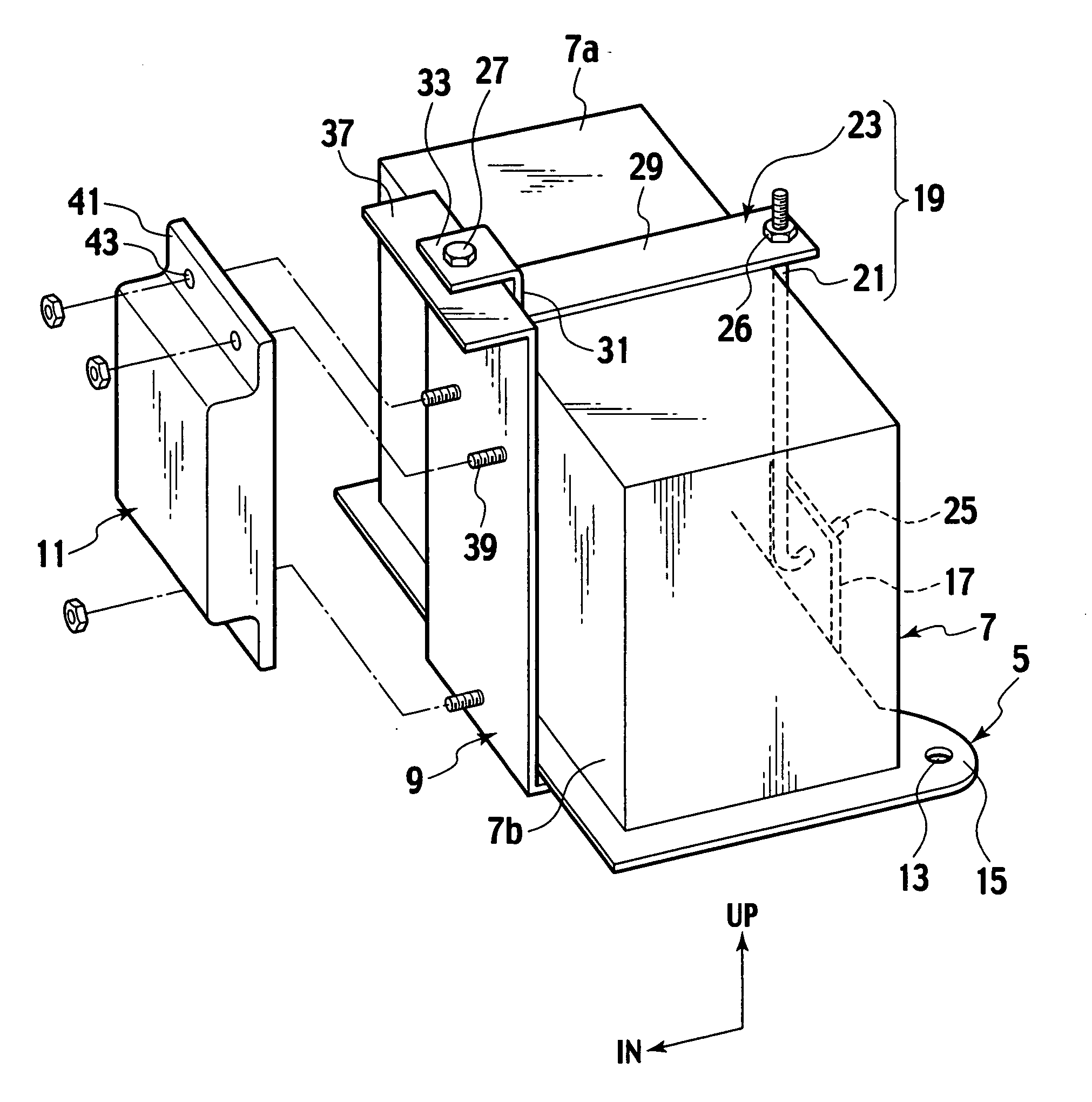
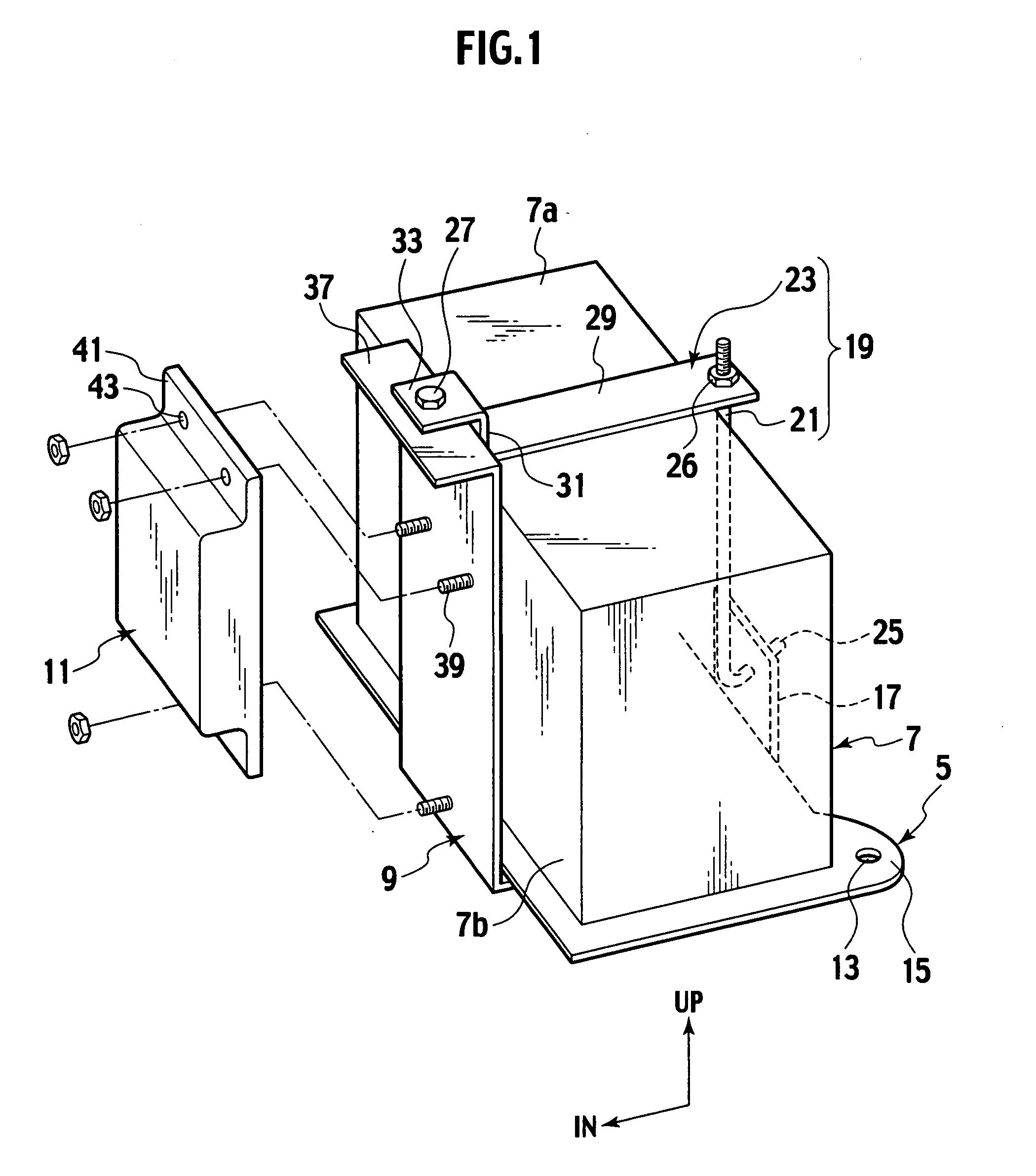
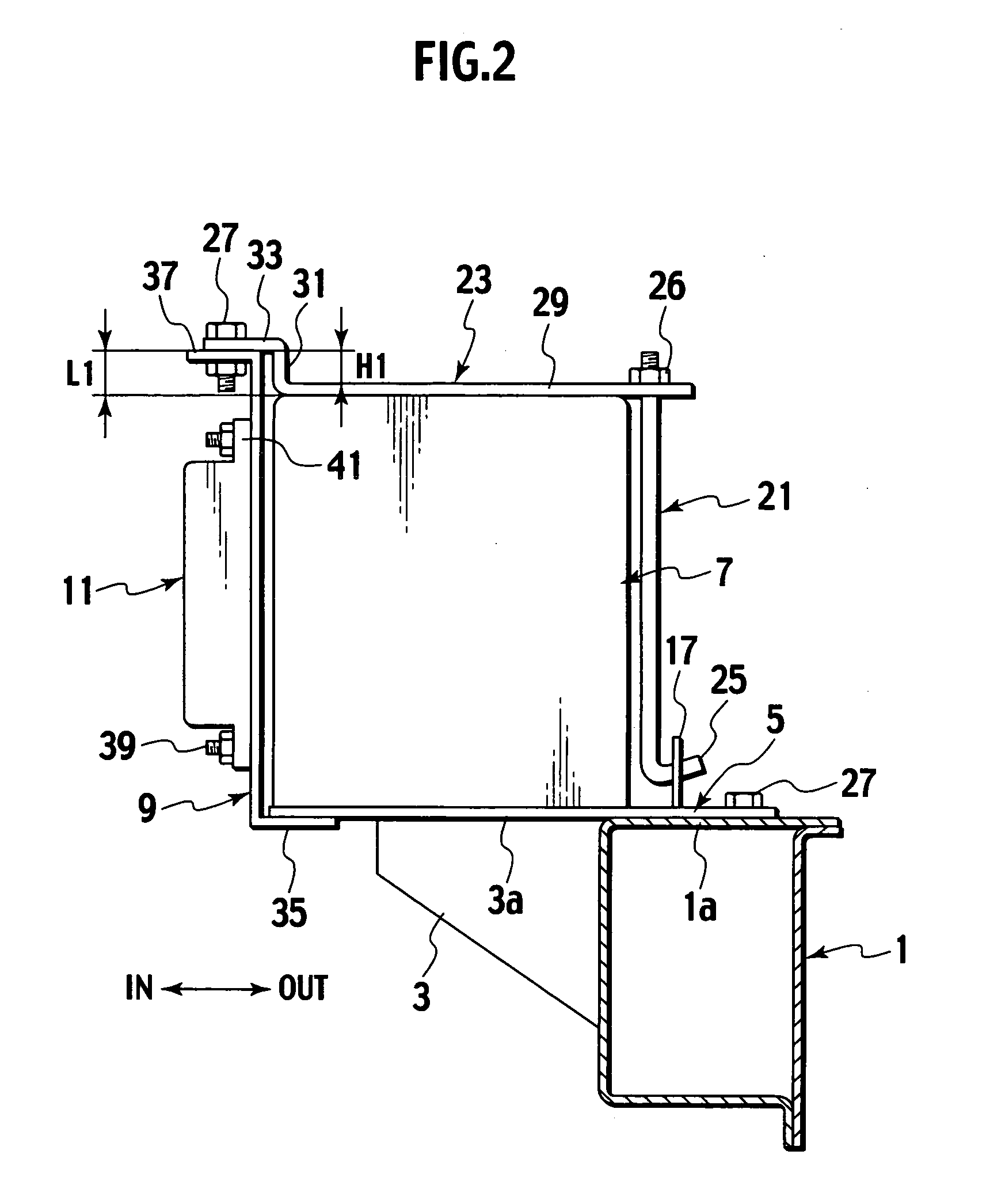
[0016] In an engine compartment of a vehicle, side members 1 are extended in the longitudinal direction of the vehicle on both right and left sides thereof. Each of the side members 1 is formed in the closed sectional structure having a rectangular shape in section, as shown in FIG. 2, and a support bracket 3 is provided on an inner side in the vehicle transverse direction of the side member 1. A top face 3a of this support bracket 3 is set at the same height as that of a top face 1a of the side member 1. And on these top faces 1a and 3a of the side member 1 and the support bracket 3, a tray 5 is provided to support a square-shaped heavy battery 7 (first part) using a retainer member 19. A fuse box 11 (second part) is supported on a bracket 9 arranged on the side of the battery 7.
[0017] The tray 5 has a top face form...
PUM
 Abstract
Description
Claims
Application Information