Plasma display panel

a technology of display panel and plasma, which is applied in the direction of address electrodes, gas-filled discharge tubes, gas-filled discharge electrodes, etc., can solve the problems of increasing the luminous efficiency of pdp, permanent image sticking, and address discharge, so as to prevent a distortion of an address signal or an increase of reactive power, reduce the distance between the address electrode and the scan electrode, and reduce the floating capacitance occurring between the adjacent address electrodes

Inactive Publication Date: 2005-10-13
SAMSUNG SDI CO LTD
View PDF16 Cites 12 Cited by
  • Summary
  • Abstract
  • Description
  • Claims
  • Application Information

AI Technical Summary

Benefits of technology

[0012] It is therefore, an object of the present invention to provide a PDP that can improve an address discharge.
[0013] It is another object of the present invention to provide a PDP that has improved luminous efficiency and reduced reactive power.
[0014] It is yet another object of the present invention to provide a PDP preventing ion sputtering of the phosphor due to the charged particles.
[0015] It is still another object of the present invention to provide a PDP that prevents burn-in of images on plasma display screen when a static image is displayed for a certain period of time.
[0019] According to the present invention, a floating capacitance occurring between the adjacent address electrodes is reduced, thereby preventing a distortion of an address signal or an increase of a reactive power.
[0020] Also, since the address electrode surrounds the discharge cell, a distance between the address electrode and the scan electrode is reduced, such that an address discharge occurs well. If the width of the horizontal portion of the address electrode is formed relatively wide, an electrode area for the address discharge is widened, thereby improving the address discharge characteristic.

Problems solved by technology

Thus, there is a limit in increasing the luminous efficiency of the PDP.
In addition, if the same image is displayed for a long time, charged particles of the discharge gas are ion sputtered on to the phosphor layers, thus causing a permanent image sticking as there is a burn-in of the image on the PDP.
Further, since a distance between the address electrode and the scan electrode is large and a width of the electrode of the address electrodes is small, there occurs a problem in an address discharge.

Method used


Image

  • Plasma display panel
  • Plasma display panel
  • Plasma display panel

Examples


Embodiment Construction

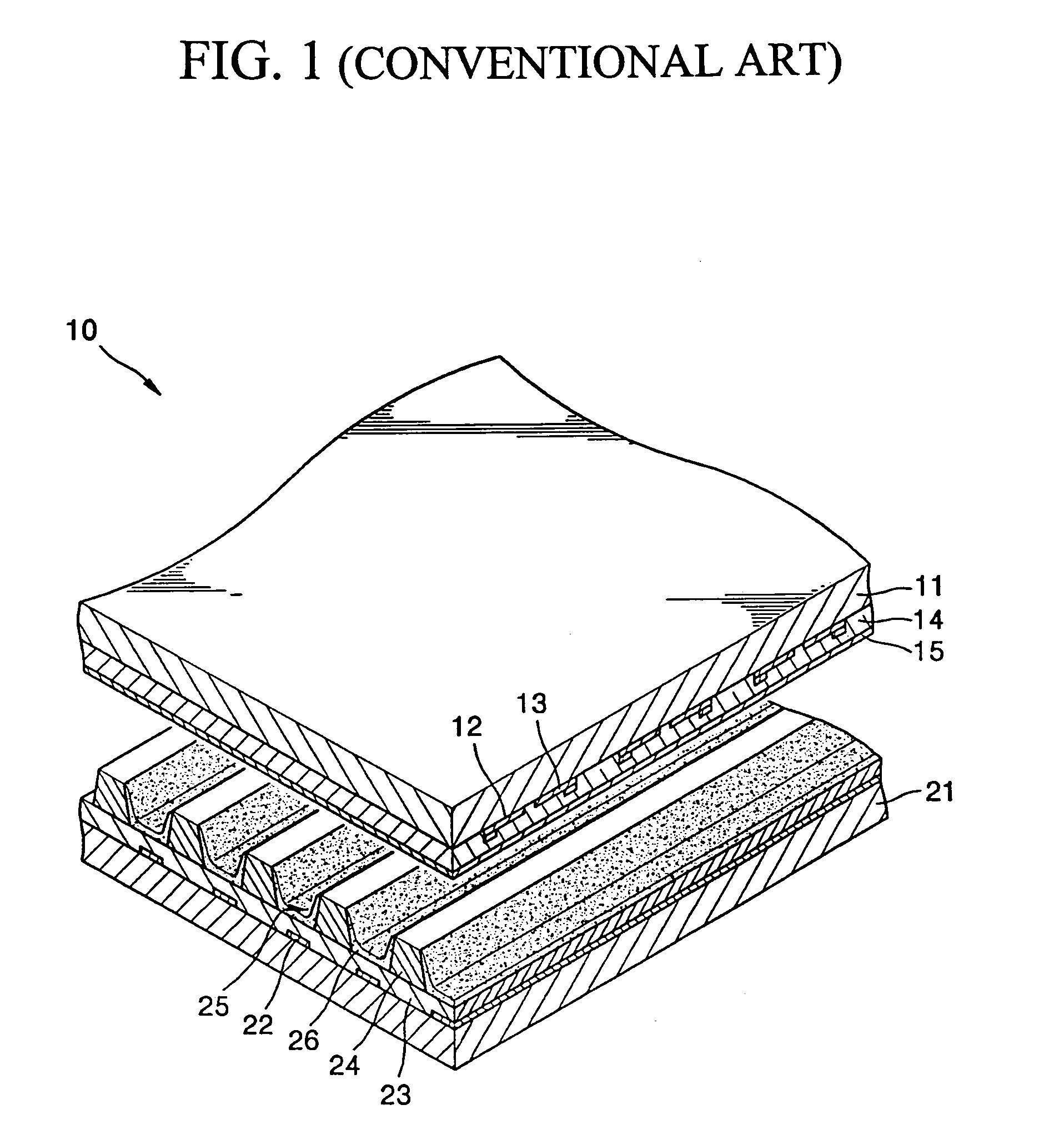
[0027] Turning now to the drawings, FIG. 1 is an exploded perspective view of a conventional triode surface discharge PDP. Referring to FIG. 1, the triode surface discharge PDP includes a front substrate 11 and a rear substrate 21 opposite to the front substrate 11.

[0028] Common electrodes 12 and scan electrodes 13 are formed below the front substrate 11. The common electrodes 12 and the scan electrodes 13 form a discharge gap. Also, the common electrodes 12 and the scan electrodes 13 are covered with a first dielectric layer 14. A protective layer 15 is formed below the first dielectric layer 14.

[0029] Address electrodes 22 are formed on the rear substrate 21 and intersect with the common electrodes 12 and the scan electrodes 13. The address electrodes 22 are covered with a second dielectric layer 23. On the second dielectric layer 23, barrier ribs 24 are spaced apart from one another by a predetermined distance that defines separating discharge spaces 25. Phosphor layers 26 are ...


PUM


Abstract

A PDP (plasma display panel) includes: a front substrate; a rear substrate arranged opposite to the front substrate; front barrier ribs arranged between the front substrate and the rear substrate and formed of a dielectric material, the front barrier ribs partitioning discharge cells together with the front and rear substrates; front and rear discharge electrodes arranged within the front barrier ribs to surround the discharge cells, and extended in parallel along discharge cells of one row; address electrodes extended along discharge cells of another row intersecting with a row of the discharge cells where the front and rear discharge electrodes are arranged; phosphor layers arranged within the discharge cells; and a discharge gas injected in the discharge cells, in which the address electrode includes discharge portions formed in a loop shape disposed at the discharge cells and connecting portions connecting the discharge portions.

Description

CLAIM OF PRIORITY [0001] This application makes reference to, incorporates the same herein, and claims all benefits accruing under 35 U.S.C. §119 from an application for PLASMA DISPLAY PANEL earlier filed in the Korean Intellectual Property Office on 9 Apr. 2004 and there duly assigned Serial No. 10-2004-0024484. BACKGROUND OF THE INVENTION [0002] 1. Field of the Invention [0003] The present invention relates to a plasma display panel having a new structure and more particularly to a plasma display panel that can improve an address discharge. [0004] 2. Description of the Related Art [0005] A plasma display panel (PDP) is a slim and light flat panel display that has large size, high definition, and wide viewing angle. Compared with other flat panel displays, the PDP can be simply manufactured in a large size and thus, is considered to be the next-generation large flat panel display. [0006] The PDP is classified into a DC (direct current) type, an AC (alternating current) type, and a ...

Claims


Application Information

Patent Timeline
Patent Type & Authority Applications(United States)
IPC IPC(8): H01J11/00H01J17/04H01J17/49
CPCH01J11/16H01J11/26H01J2211/265H01J2211/326H01J2211/363
Inventor WOO, SEOK-GYUNHONG, CHONG-GI
Owner SAMSUNG SDI CO LTD
Why Eureka
Try Eureka