
Holder for conductive contact

a technology of conductive contact and probe holder, which is applied in the direction of electrical testing, measurement devices, instruments, etc., can solve the problems of dimensional errors produced in the holder, the positional precision of the contact point of each contact unit, and the pitch change between adjacent holder holes, so as to achieve the effect of increasing the mechanical strength of the thread, increasing the fastening force of the threaded bolt, and high strength

Inactive Publication Date: 2005-10-13
NHK SPRING CO LTD
View PDF6 Cites 20 Cited by
  • Summary
  • Abstract
  • Description
  • Claims
  • Application Information

AI Technical Summary

Benefits of technology

[0008] In view of such problems of the prior art, a primary object of the present invention is to provide a contact probe holder that can ensure a high level of positional precision to the contact points while simplifying the manufacturing process.
[0009] A second object of the present invention is to provide a contact probe holder that can be reduced in thickness without compromising the mechanical strength thereof.
[0010] A third object of the present invention is to provide a contact probe holder that is favorable in terms of both electric and mechanical properties.

Problems solved by technology

However, according to this arrangement, because each of the insulating members that form the holder consists of a single piece member made of plastic material, dimensional errors may be produced in the holder over time owing to the change in temperature during the test (test under a high temperature condition), residual stress produced by a machining or other working process and absorption of moisture.
Such dimensional errors give rise to changes in the pitch between adjacent holder holes and the positional precision of the contact point of each contact unit (the position of the tip of the needle member) may be impaired.

Method used


Image

  • Holder for conductive contact
  • Holder for conductive contact
  • Holder for conductive contact

Examples


Embodiment Construction

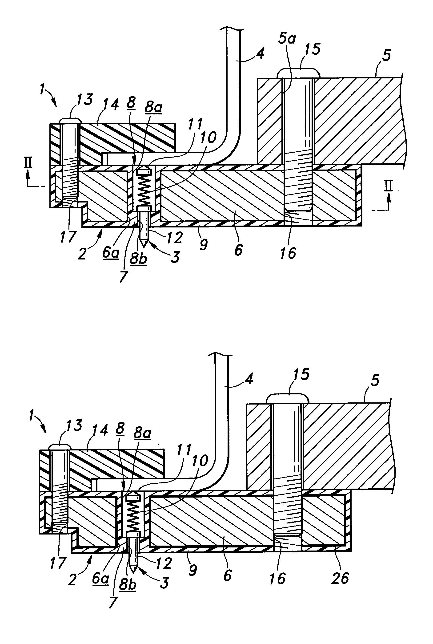
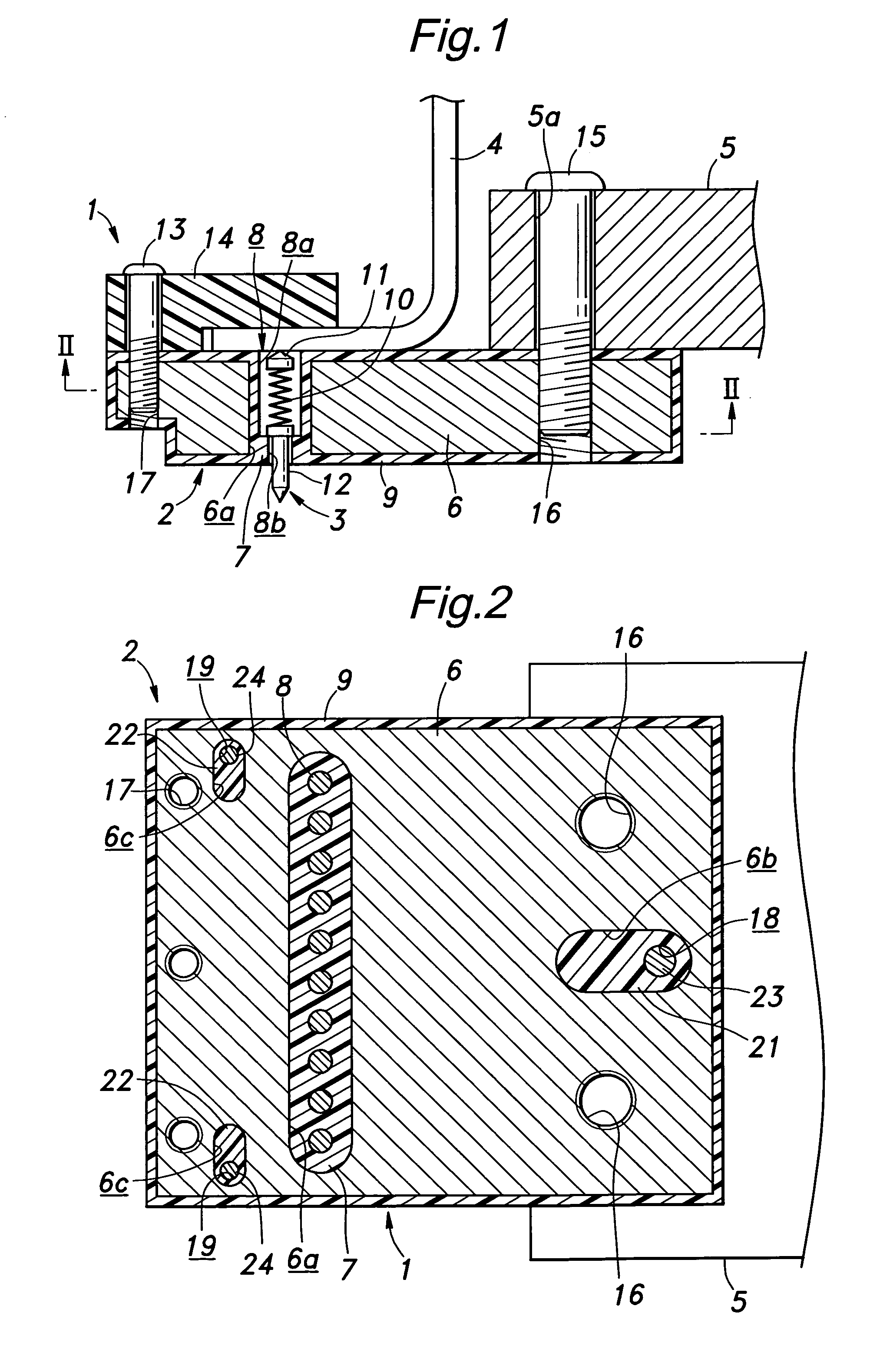
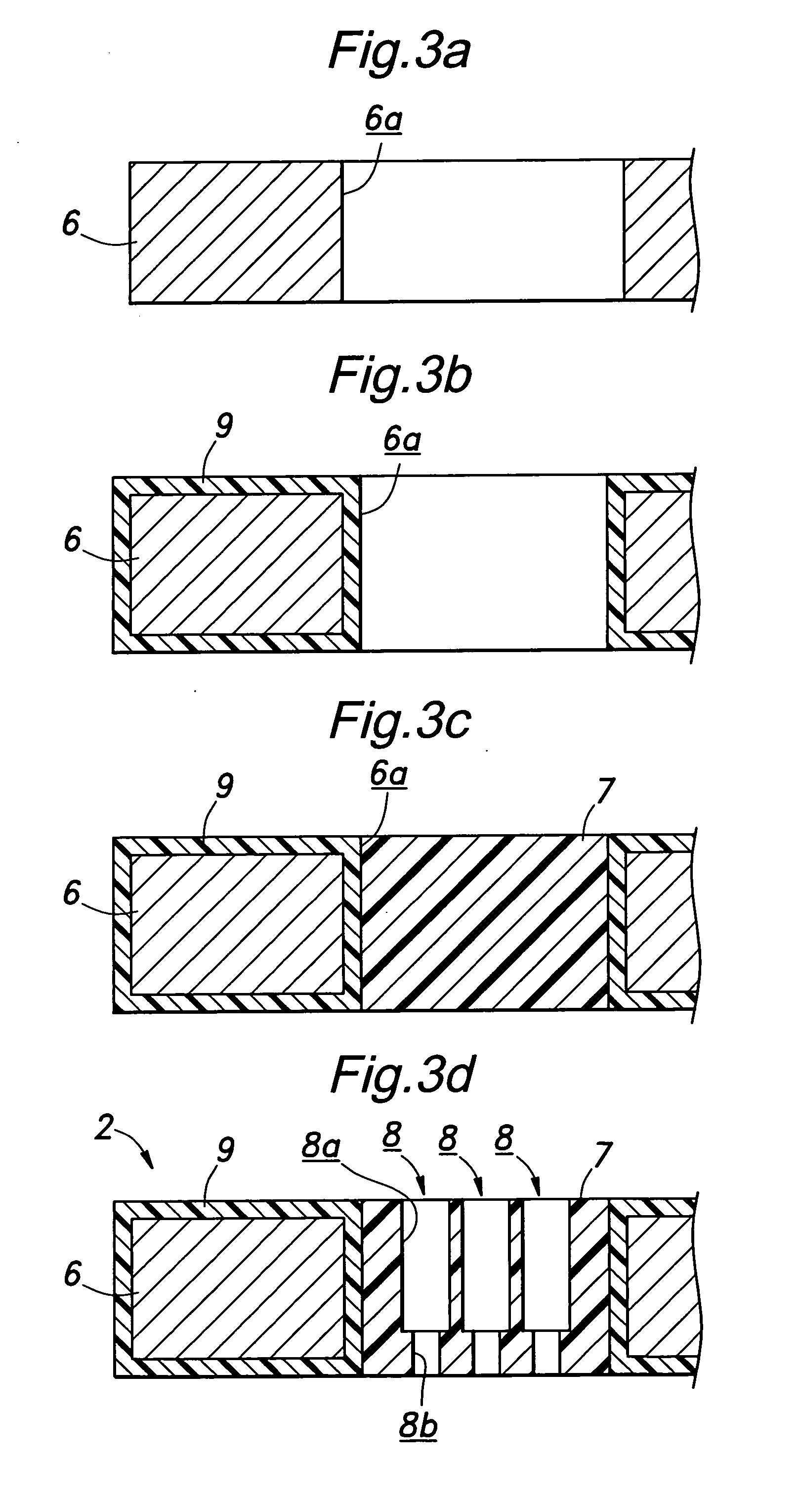
[0037]FIG. 1 is a schematic longitudinal sectional view of a contact probe using a contact probe holder embodying the present invention, and FIG. 2 is a sectional view taken along line II-II of FIG. 1. As shown in the drawings, the illustrated contact probe 1 comprises a holder 2 in the form of a plate member, a plurality of contact units 3 which are arranged in two locations of the holder 2, and a circuit board 4 for electrically connecting the contact units 3 with a testing device not shown in the drawings. The illustrated contact probe may be used for testing LCD panels before completion as was the case with the conventional contact probe, and is adapted to be vertically moveable in the drawings by using an arm 5 of an actuator to access the terminals (not shown in the drawings) of an LCD panel placed in a lower part as seen in the drawing for applying the contact probe 3 thereto for a testing purpose.

[0038] The holder 2 comprises a high strength base plate 6 made of a heat resi...


PUM


Abstract

A holder supported by an arm comprises a metallic reinforcing member and a plastic holder hole forming member filled in an opening formed in the reinforcing member. Holder holes are formed in the holder hole forming member, and a coil spring and electroconductive needle members are installed in each holder hole to thereby provide a contact probe having two moveable ends. Because the holder is essentially made of the metallic member, the mechanical strength of the holder can be improved over that formed strictly from plastic material. Therefore, the contact probe holder would not suffer from dimensional changes of the holder owing to aging compounded by temperature changes for testing (tests under high temperature conditions) and residual stress so that the change in the pitch of the holder holes can be avoided, and a high level of precision can be ensured. Therefore, the contact probe allows tests to be conducted in a stable manner over an extended period of time.

Description

TECHNICAL FIELD [0001] The present invention relates to an electroconductive contact probe holder that can be used for passing electric signals to and from printed circuit boards, electronic devices or the like. BACKGROUND OF THE INVENTION [0002] Contact units that are used in contact probes for electrically testing conductive patterns of printed circuit boards and electronic devices include those having a pair of needle members that are disposed so as to be moveable in the axial direction on either axial end as disclosed in Japanese UM laid open publication No. 60-154868. Such an electroconductive contact unit having two moveable ends is typically used for temporarily connecting, for testing purposes, two circuit boards that are eventually permanently connected in the final product. LCD panels and array circuit boards can be tested by using a contact probe having a same number of contact units as the number of electrodes in the circuit pattern of the LCD panel. The testing of the L...

Claims


Application Information

Patent Timeline
Patent Type & Authority Applications(United States)
IPC IPC(8): G01R1/073
CPCG01R1/07314G01R1/0466G01R1/0483G01R1/06
Inventor KAZAMA, TOSHIONAGAYA, MITSUHIROSOTOMA, HIROYASU
Owner NHK SPRING CO LTD
Learn More