Calibration camera device and calibration system

a camera and camera technology, applied in the field of calibration system, can solve the problems of deteriorating the displaying affecting the quality of the image displaying device, so as to achieve good dustproof

Inactive Publication Date: 2005-10-13
OLYMPUS CORP
View PDF8 Cites 16 Cited by
  • Summary
  • Abstract
  • Description
  • Claims
  • Application Information

AI Technical Summary

Benefits of technology

[0008] It is a first object of the present invention to provide a not expensive and small calibration camera device with good dustproof wherein in order to realize an image quality as designed, geometrical correction and color correction can be conducted by itself by selecting and using optical filters as desired.
[0009] It is a second object of the present invention to provide a calibration system which is preferably employed in the image quality control of a table displaying device by using a not expensive and small calibration camera device with good dustproof wherein geometrical correction and color correction can be conducted by itself.
[0058] According to the invention of claim 4, since the motor is a step motor, the operation of the filter switching mechanism of any one optical filter being selected from among the three through eight optical filters and disposed at the photometric point on the optical path” can be easily conducted.

Problems solved by technology

At each projector, however, may occur geometrical distortion, color shading, luminance shading, difference in gamma characteristic, difference in white balance and the like.
In this case, the differences in image quality between the projectors become conspicuous, thereby deteriorating the displaying quality of the image displaying device.
With the calibration camera device disclosed in Patent Publication No. 1, since the 16 (in fact, 15) interference filters are employed to constitute the 16 band camera, the size of the calibration camera device is enlarged and the cost of the calibration camera device is increased due to the use of the expensive interference filters.
In this case, even though the calibration camera device is employed, the image quality of an image projected from the multi-displaying device may be deteriorated.

Method used


Image

  • Calibration camera device and calibration system
  • Calibration camera device and calibration system
  • Calibration camera device and calibration system

Examples


first embodiment

[0082] In this embodiment, a calibration camera system is composed of the calibration camera device of the first embodiment, and as shown in FIG. 5, is composed of a calibration camera device 21 (for easy explanation, only a part corresponding to the photometric point P is illustrated), a ceiling camera attaching unit 23 as a fixing member to fix the calibration camera device 21 to a given structural body (in this embodiment, a ceiling 22) and an reflective mirror 24 which is provided in front of the calibration camera device 21 on the optical path and which deflects the optical path by a given angle. The calibration system is configured so that the geometrical correction and the color correction are conducted on a test pattern image which is displayed on a screen 27 of a table displaying device 26 positioned on a floor 25 on the deflected optical path and is captured. In FIG. 5, in the attachment of the calibration camera device 21 on the ceiling 22 positioned directly above the sc...

second embodiment

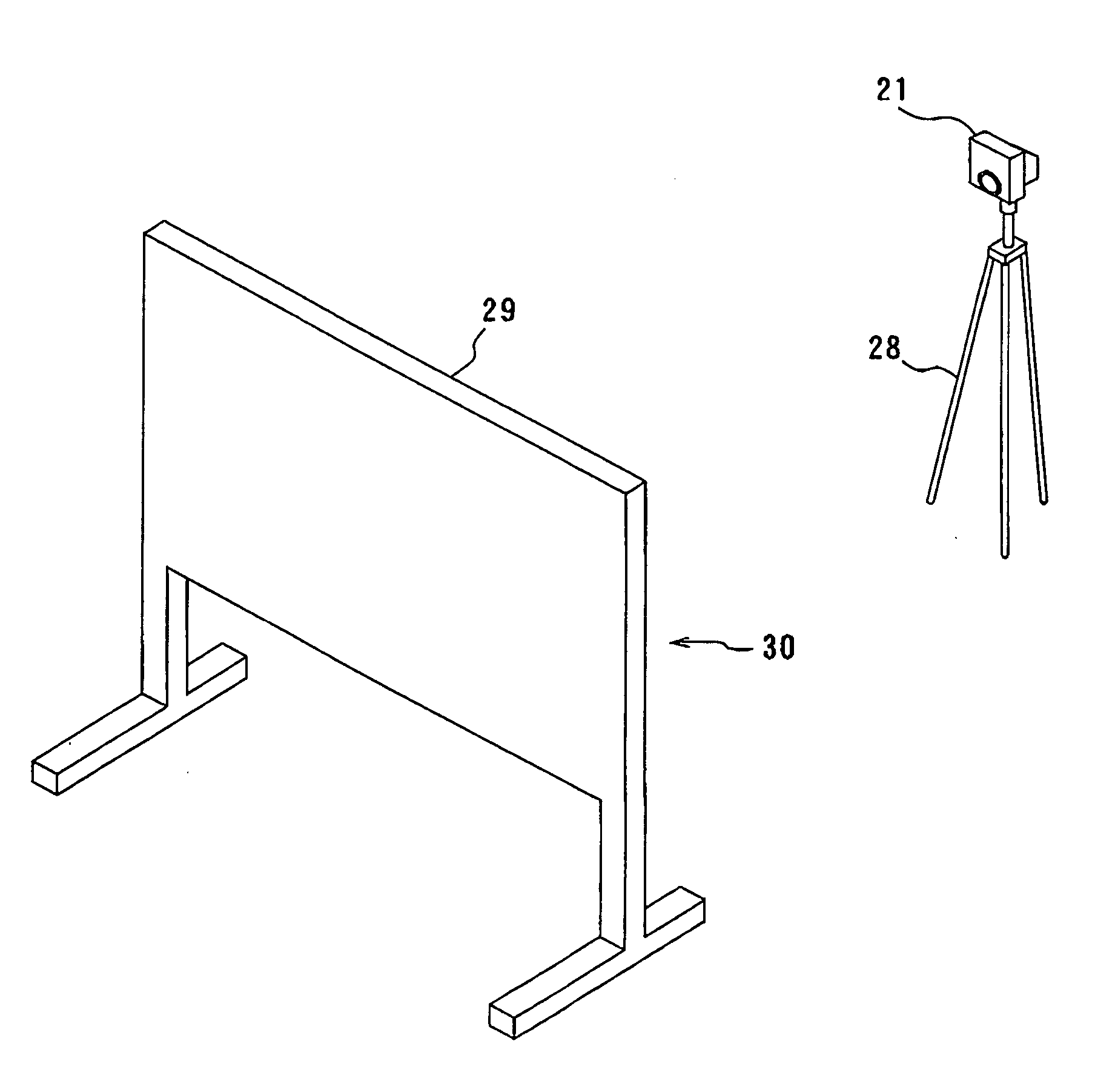
[0084] In this embodiment, a calibration camera system is composed of the calibration camera device of the first embodiment, and as shown in FIG. 6, is composed of the calibration camera device 21, a tripod stand to support the calibration camera device almost horizontally and a vertical displaying device 30 which is provided in front of the calibration camera device 21 on the optical path and has a vertical screen 29. The calibration system is configured so that the geometrical correction and the color correction are conducted on a test pattern image which is displayed on the vertical screen 29 and captured. A projector to photograph an image may be provided in front of or the rear of the vertical screen.

[0085] According to the calibration camera system of this embodiment, since the not expensive and small calibration camera device with good dustproof can be provided wherein the geometrical correction and the color correction can be conducted by itself is employed, the calibration...


PUM


Abstract

A calibration camera device for geometrical correction or color correction, including a camera mechanism containing a lens, a near-infrared light cutting filter and an imaging element, an optical filter mechanism with three through eight optical filters which is provided in front of the lens, a filter switching mechanism to select any one from among the optical filters and dispose the selected one optical filter at a photometric point, an external cover having an opening formed in front of the lens and covering the optical filter mechanism, the filter switching mechanism and the camera mechanism, an dustproof transparent member to be attached to the opening of said external cover, and a controller which includes an image storing part to store an image captured by the imaging element and a correction information generating part to generate correction data on the image.

Description

BACKGROUND OF THE INVENTION [0001] 1. Field of the Invention [0002] The present invention relates to a calibration camera device which can be used in geometrical correction in combination with color correction by itself and to a calibration system which is preferably used in image quality control of a table image displaying device and the like to display different images on corresponding divided areas of a screen. [0003] 2. Description of the Related Art [0004] Conventionally, an image displaying device has been proposed wherein a plurality of images are projected from the corresponding projectors and synthesized as one large image on one screen. At each projector, however, may occur geometrical distortion, color shading, luminance shading, difference in gamma characteristic, difference in white balance and the like. In this case, the differences in image quality between the projectors become conspicuous, thereby deteriorating the displaying quality of the image displaying device. I...

Claims


Application Information

Patent Timeline
Patent Type & Authority Applications(United States)
IPC IPC(8): H04N5/225G02B7/00H04N5/232H04N17/00H04N17/02
CPCG02B7/006H04N17/002G02B26/008
Inventor SADANO, IKUHARU
Owner OLYMPUS CORP
Why Eureka
Try Eureka