Optical fiber tape core

a technology of optical fiber and core, applied in the field of optical fiber ribbon, can solve the problems of temporary increase in loss of optical fiber in use, adverse influence of loss on communication employing optical fiber, etc., and achieve the effects of reducing adverse influences on communication, wide band, and high quality

Inactive Publication Date: 2005-10-13
SUMITOMO ELECTRIC IND LTD
View PDF7 Cites 31 Cited by
  • Summary
  • Abstract
  • Description
  • Claims
  • Application Information

AI Technical Summary

Benefits of technology

[0011] In the optical fiber ribbon according to the present invention, it is still also preferrable that the transmission loss of said plurality of optical fibers at a wavelength of 1.3 μm is 0.5 dB / km or less respectively. Further, it is preferred that the absolute value of the wavelength dispersion in the plurality of optical fibers at a wavelength of 1.3 μm and at a wavelength of 1.55 pm is 12 ps / nm / km or less respectively. In the above cases, a long distance optical transmission with a high quality and wide band is made possible.
[0012] In the optical fiber ribbon according to the present invention, it is furthermore preferred that an amount of the change in the loss at a wavelength of 1.55 μm at single optical fiber separation is 1.0 dB or less per optical fiber. The optical fiber ribbon preferably has the thickness (the maximum value of the distance from the optical axis center to the ribbon matrix surface of each optical fiber) of 155 μm or less in the direction perpendicular to the plane of the juxtapositional arrangement pertaining to plurality of optical fibers juxtaposed in parallel to each other. It is much more preferable that the thickness is less than 150 μm. It is preferred that each of said plurality of optical fibers is covered with a color layer, and adhesion force between said color layer and said ribbon matrix in a 180° peel test is 0.4-5.0 g / cm. Further, it is preferred that the thickness of the ribbon matrix to be determined in the thickness direction perpendicular to the plane of the juxtapositional arrangement is larger where same direction is associated with a supposed directional line extending through a location between optical fibers, than in case where same direction is associated with a supposed directional line extending through a center of any one of the optical fibers. In the above cases, since an amount of the change in the loss on the occasion of a single optical fiber separation is sufficiently small, even in the event that any of the optical fibers is used for communication purposes, it is possible to sufficiently reduce adverse influences exerted on the communication.
[0013] In the optical fiber ribbon according to the present invention, it is preferred that each of the plurality of optical fibers has passed successfully a proof test of elongation strain of 1.5% or more. In this case, when represented based on the Mitsunaga theory (J. Appl. Phys. (1982) 53), after the optical fibers has been placed being bent at a bending diameter of 30 mm for 20 years, the fracture probability is 1×10⁻⁵ / km or less. Further, it is preferred that each of said plurality of optical fibers has passed successfully in a proof test of elongation strain of 2.5% or more. In this case, after the optical fibers has been placed being bent at a bending diameter of 15 mm for 20 years, the fracture probability is 1×10⁻⁵ / km or less. Furthermore, it is preferred that the fatigue coefficient of said plurality of optical fibers is 50 or more respectively. In this case, after the optical fibers has been placed being bent at a bending diameter of 30 mm for 20 years, the fracture probability is 1×10⁻⁵ / km or less. In the above cases, in the optical fiber ribbon, even in the event of being bent to a small bending diameter, there is ensured a long term reliability.
[0014] In the optical fiber ribbon according to the present invention, it is preferred that the difference between the maximum value and the minimum value in the cladding diameter of said plurality of optical fibers is 1.0 μm or less. In this case, it is possible to reduce the connection loss between an optical fiber and an optical connector.
[0015] In the optical fiber ribbon according to the present invention, it is preferred that the thickness of the protective coating of said plurality of optical fibers is 15-37.5 μm respectively. Further, it is preferred that the protective coating of said plurality of optical fibers is comprised of a single layer respectively, and the Young's modulus of the protective coating is 10 kg / mm2 or more. Furthermore, it is preferred that the protective coating of said plurality of optical fibers is comprised of a double layer respectively, the thickness of the both layers is 15-37.5 μm, the Young's modulus of the inner protective coating is 0.2kg / mm2 or less, and the Young's modulus of the outer protective coating is 10 kg / mm2 or more. In the above cases, since each of the optical fibers can be reduced in diameter, an optical fiber ribbon in which optical fibers are arranged with high density can be achieved.
[0016] The optical fiber ribbon according to the present invention is an optical fiber ribbon comprised of the plurality of optical fibers arranged in parallel to each other being covered with the ribbon matrix, wherein, in each of the plurality of optical fibers, the mode field diameter defined by the definition of Petermann-I at a wavelength of 1.55 μm is 8 μm or less; the cable cutoff wavelength is 1.26 μm or less; and bending loss with a bending diameter of 15 mm at a wavelength of 1.55 μm is 0.1 dB / turn or less. The optical fiber ribbon having the characteristics as described above is excellent in bending property, and hence, even when the separation of a single optical fiber is performed in a midway portion, it is possible to prevent the loss from increasing.

Problems solved by technology

Under such circumstances, supposing the separation of a single optical fiber is performed at a midway portion, fingers may touch an optical fiber in use, or an optical fiber in use may be sharply bent using a tool, whereby the loss pertaining to the optical fiber in use may temporarily increase.
Such increase in the loss may exert any adverse influence upon the communication employing the optical fiber.

Method used


Image

  • Optical fiber tape core
  • Optical fiber tape core
  • Optical fiber tape core

Examples


embodiment 1

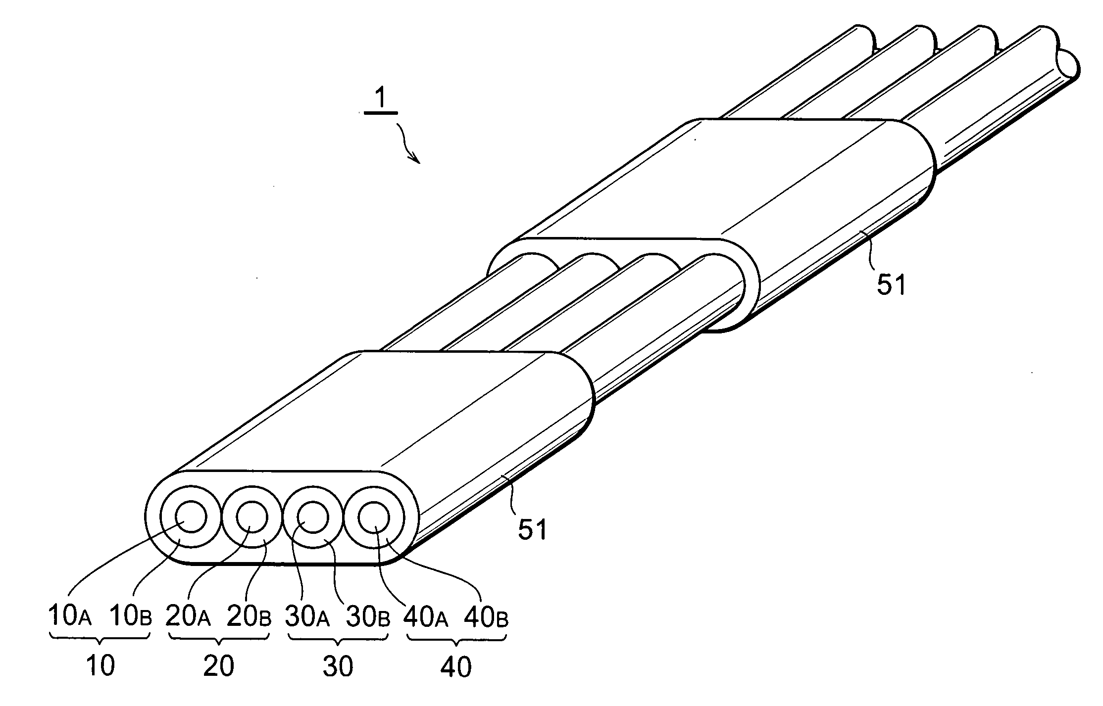
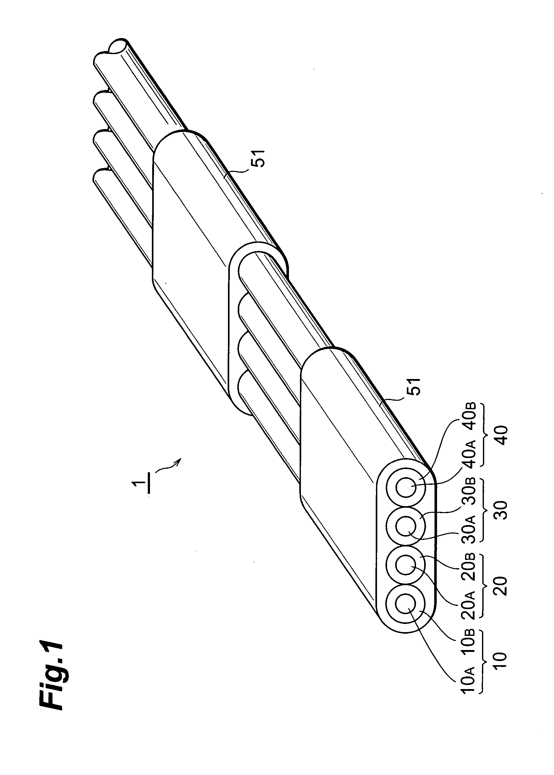
[0037] Particularly, in the optical fiber ribbon 1 , there alternate with each other first areas covered with the ribbon matrix 51 and second areas uncovered with the ribbon matrix along the longitudinal direction. The length in the longitudinal direction of the first areas and the second areas is preferably 10-300 mm. When the length of the first areas is shorter than 10 mm, there is a possibility that the ribbon matrix 51 is accidentally divided. When the length of the first areas is longer than 300 mm, it is hard to separate a single optical fiber. Also, when the length of the second areas is shorter than 10 mm, it is hard to separate a single optical fiber. When the length of the second areas is longer than 300 mm, there is a possibility that the ribbon matrix 51 is accidentally divided.

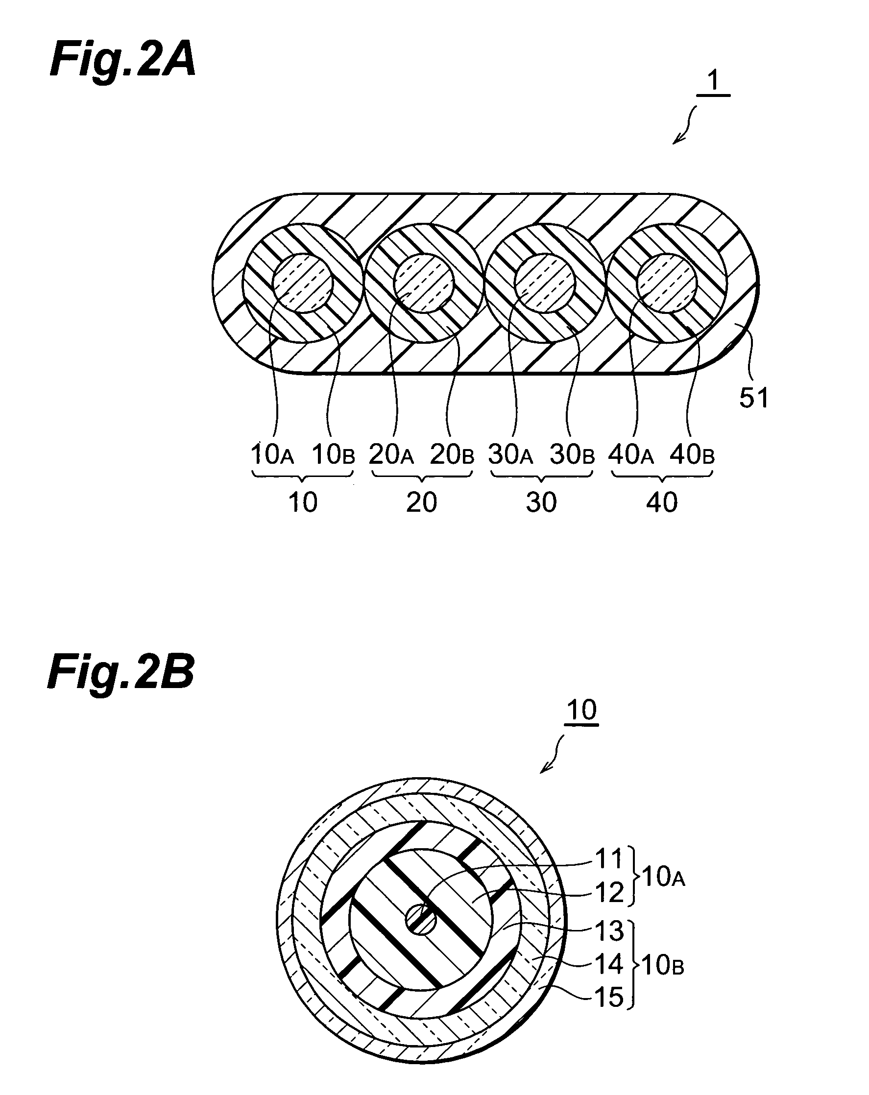
[0038] The ribbon matrix 51 is comprised of, for example, a UV curable resin, and the thickness thereof is preferably equal to the radius or less of each optical fiber. The first areas and the se...

embodiment 2

[0042] The optical fiber ribbon can be fabricated by applying the ribbon matrix by means of a coating die having a hole with a shape of section formed in such a manner that the thickness of the optical fiber ribbon becomes smaller in the position between the optical fibers each other.

[0043]FIG. 4 is a perspective view of an optical fiber ribbon 3 according to Embodiment 3. FIG. 5 is a sectional view of the optical fiber ribbon 3 according to the Embodiment 3. In the optical fiber ribbon 3, four optical fibers 10, 20, 30 and 40 are arranged in apparel in juxtaposition with each other in a certain plane, whereas a part of the periphery of the four optical fibers is covered with a ribbon matrix 53, but the rest thereof is not covered with the ribbon matrix. The ribbon matrix 53 is comprised of, for example, a UV curable resin, and the thickness thereof is preferably as large as the size of the radius of each optical fiber or less. Particularly, in the optical fiber ribbon 3 according ...

embodiment 4

[0046] The optical fiber ribbon can be formed by, immediately after the ribbon matrix is applied by a dispenser, removing the ribbon matrix in the sunken portions with a butt strap plate or the like, and then curing the remaining ribbon matrix.

[0047]FIG. 7 is a perspective view of an optical fiber ribbon 5 according to Embodiment 5. FIG. 8 is a sectional view of the optical fiber ribbon 5 according to the Embodiment 5. In the optical fiber ribbon 5, four optical fibers 10, 20, 30 and 40 are arranged in parallel to each other in a plane, and a part of the periphery of the four optical fibers is covered with a ribbon matrix 55, but the rest thereof is not covered with the ribbon matrix. The ribbon matrix 55 is comprised of, for example, a UV curable resin and the thickness thereof is preferably equal to the radius or less of each optical fiber. Particularly, the optical fiber ribbon 5 according to the Embodiment 5, first areas covered with the ribbon matrix 55 and second areas not co...


PUM


Abstract

In an optical fiber ribbon 1 according to the present invention, four optical fibers 10, 20, 30 and 40 are arranged in parallel to each other in a plane, a part of the periphery of these four optical fibers is covered with a ribbon matrix 51, but no rest thereof is covered with the ribbon matrix. First areas covered with the ribbon matrix 51 and second areas uncovered with the ribbon matrix alternate with each other along the longitudinal direction thereof. Alternatively, the optical fiber ribbon 1 is covered with the ribbon matrix over its entire length. In the glass section of each optical fibers, the mode field diameter defined by the definition of Petermann-I at a wavelength of 1.55 μm is 8 μm or less, and the cable cutoff wavelength is 1.26 μm or less.

Description

TECHNICAL FIELD [0001] The present invention relates to an optical fiber ribbon comprising a plurality of optical fibers arranged in parallel in juxtaposition with each other and covered with a ribbon matrix. BACKGROUND ART [0002] The optical fiber ribbon is comprised of a plurality of optical fibers, wherein the plurality of optical fibers are placed in parallel in juxtaposition with each other and covered with a ribbon matrix. When the optical fiber ribbon as described above is employed, the separation of a single optical fiber is performed at the end of the optical fiber ribbon, with respect to each optical fiber whereupon the front end of each optical fiber is connected to an optical connector. By means of the optical connector, there takes place input or output of a signal light for each optical fiber. [0003] For example, in optical fiber ribbons disclosed in Japanese Unexamined Utility Model Publication No. S61-185008 and Japanese Unexamined Utility Model Publication No. H4-75...

Claims


Application Information

Patent Timeline
Patent Type & Authority Applications(United States)
IPC IPC(8): G02B6/02G02B6/36G02B6/44
CPCG02B6/02004G02B6/02266G02B6/02271G02B6/0281G02B6/02395G02B6/3636G02B6/4403G02B6/4495G02B6/03611G02B6/4431G02B6/44
Inventor OKUNO, KAORUHATTORI, TOMOYUKI
Owner SUMITOMO ELECTRIC IND LTD
Why Eureka
Try Eureka