Fluid flow guide element and fluid flow apparatus equipped therewith

Inactive Publication Date: 2005-10-13
NOORKAMI JAMSHID
View PDF11 Cites 2 Cited by
  • Summary
  • Abstract
  • Description
  • Claims
  • Application Information

AI Technical Summary

Benefits of technology

[0032] As a result of the spiral flow induced due to the recesses or elevations, the oncoming flow is made more uniform, thus permitting in particular significant improvements in efficiency in comparison with conventional diffusers. It is thus possible here to rel

Problems solved by technology

It is known from the boundary layer theory that flows with a pressure increase are at high risk of separation.
However, such separation results in high flow losses.
In particular, a sudden widening of cross section results in

Method used


Image

  • Fluid flow guide element and fluid flow apparatus equipped therewith
  • Fluid flow guide element and fluid flow apparatus equipped therewith
  • Fluid flow guide element and fluid flow apparatus equipped therewith

Examples


Embodiment Construction

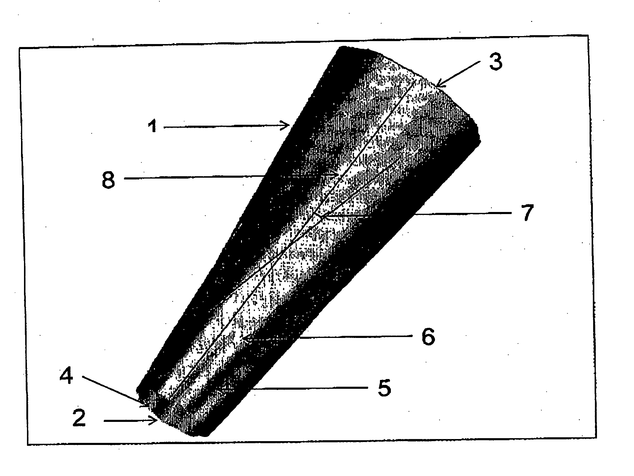
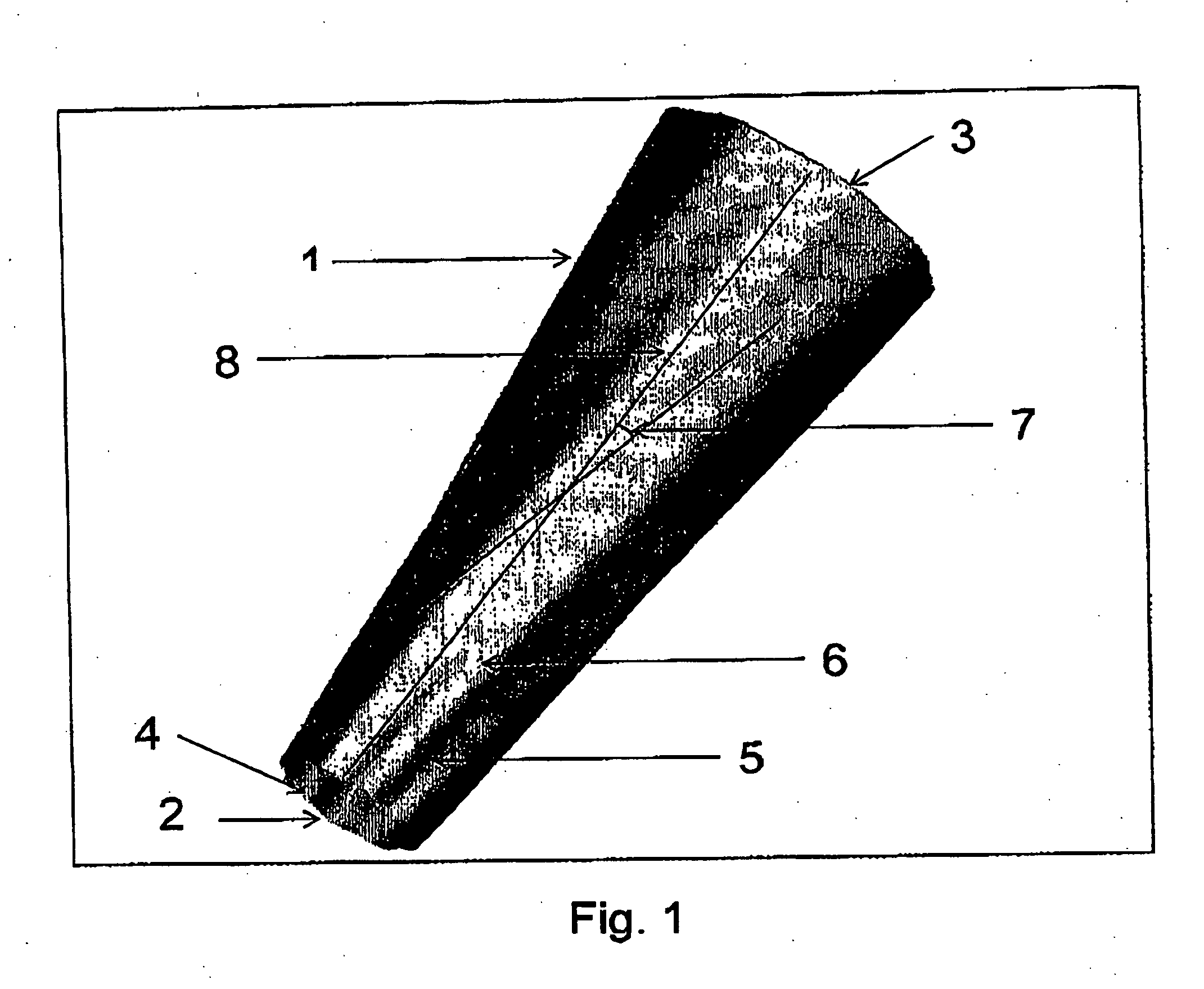
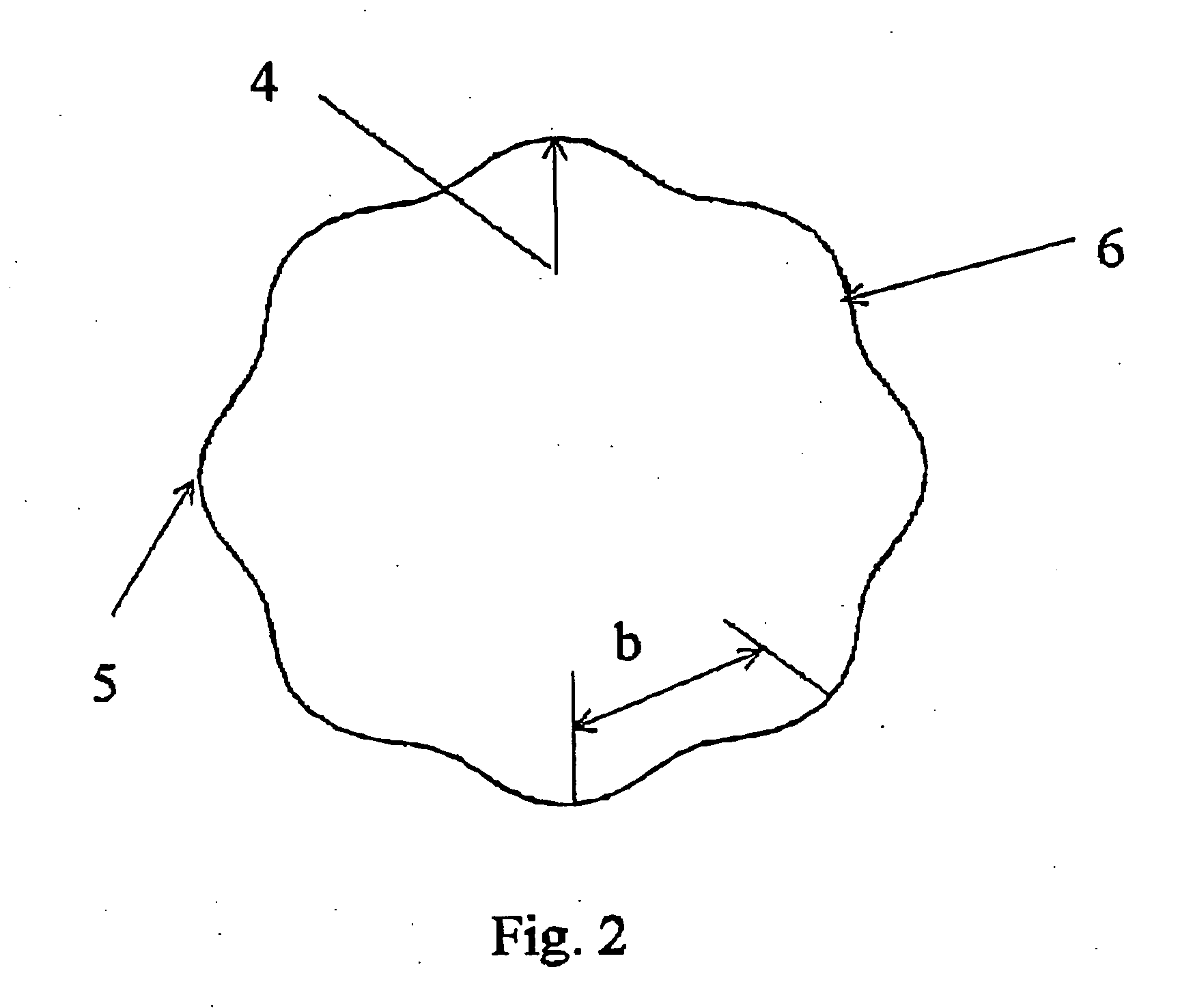
[0037]FIG. 1 shows a perspective view of a fluid flow guide element 1 according to the invention, constructed in particular as a diffuser. The fluid flow guide element 1 has an inlet opening 2 and an outlet opening 3, whose cross-sectional areas differ from one another, as shown in greater detail in FIGS. 2 and 3. On the outside there is a structuring which is also reflected on the inside and is arranged in the form of a spiral on an inside wall surface 4 of the fluid flow guide element 1 and is composed of recesses 5 and elevations 6 having a predetermined inclination 7 with respect to a longitudinal axis 8 of the fluid flow guide element 1. The recesses 5 and / or elevations 6 extend continuously and increase in size steadily between the inlet opening 2 and the outlet opening 3, whereby the width b of the recesses 5 and the elevations 6 increases steadily from the inlet opening 2 to the outlet opening 3. This makes it possible to achieve a large opening angle without limiting the ef...


PUM


Abstract

A fluid flow guide element (1) constructed, for example, as a diffuser having an inlet opening (2) and an outlet opening (3) whose respective cross-sectional areas differ from one another. Corresponding to the exterior view shown in FIG. 1, the inside wall surface (4) of the fluid flow guide element (1) is provided with spirally arranged recesses (5) and elevations (6) having an inclination (7) relative to a longitudinal axis (8) of the guide element (1). The recesses (5) and/or elevations (6) have a width that increases or decreases steadily between the inlet opening (2) and the outlet opening (3). This facilitates efficient operation of a fluid flow guide element (1) which simultaneously has both a large opening angle and a reduced design length by achieving a more uniform flow or flow profile due to the spiral arrangement of the recesses (5) and elevations (6).

Description

BACKGROUND OF THE INVENTION [0001] The present invention relates to a fluid flow guide element having an inlet opening and an outlet opening, with structuring provided on an inside wall surface of the fluid flow guide element and equipped with recesses and / or elevations, having a predetermined inclination with respect to the longitudinal axis of the fluid flow guide element in the form of a slope. In addition, this invention relates to a fluid flow apparatus equipped with such a fluid flow guide element. [0002] A fluid flow guide element of this type constructed as a diffuser or a nozzle is already widely used in practice, especially in large-scale industrial plants for energy production and in internal combustion engines. [0003] The diffuser serves to recover kinetic fluid energy, with an increase in the static pressure occurring in the direction of flow. In this case kinetic energy is converted to potential energy. Such an energy conversion is desirable in many technical applicati...

Claims


Application Information

Patent Timeline
IPC IPC(8): B05B1/34F01D1/22F15D1/02F15D1/06F16K31/12
CPCF15D1/065F02K1/48
Inventor NOORKAMI, JAMSHID
Owner NOORKAMI JAMSHID
Why Eureka
Try Eureka