Method for warming-up an LCD (liquid crystal display) system

Active Publication Date: 2005-10-13
AU OPTRONICS CORP
View PDF12 Cites 13 Cited by
  • Summary
  • Abstract
  • Description
  • Claims
  • Application Information

AI Technical Summary

Benefits of technology

[0010] According to a second aspect of the present invention, a method for warming-up an OCB mode LCD system is proposed, wherein the LCD system includes a pixel array having a plurality of pixel units, each of the pixel units including a pixel electrode, and a TFT (thin film transistor) provide with a source, a drain and a gate such that a gate signal with a high or low voltage level inputted into the gate can switch on or switch off the TFT so as to permit transfer of a data signal from the source to the pixel electrode. A common electrode is disposed oppositely to the pixel electrode. A liquid crystal layer is sandwiched between the pixel electrode and the common electrode. The warming-up method of the present invention includes the steps: floating the source of the TFT during a front section of a warming-up operation, and simultaneously applying the gate signal with the high voltage level onto the gate which is coupled to the pixel electrode in such a manner that the pixel electrode possesses a voltage level which is substantially equal to that of the gate signal, wherein the pixel electrode with the voltage level enables quick transition of liquid crystal molecules in the liquid crystal layer from a splay alignment into a bend alignment; and restoring the transfer of the data signal inputting the source at a rear section of the warming-up operation, and simultaneously applying the gate signal with the high voltage level onto the gate ceaselessly, thereby permitting the transfer of the data signal from the source to the pixel electrode.
[0011] According to a third aspect of the present in

Problems solved by technology

Such type of bent alignment can result in fast switching retardation of light.
Note that, though the OCB mode LCD system has the aforesaid advantage, there still exist some disadvantages, such as it requires a longer warming-up time in order to perform the transition of the liquid c

Method used


Image

  • Method for warming-up an LCD (liquid crystal display) system
  • Method for warming-up an LCD (liquid crystal display) system
  • Method for warming-up an LCD (liquid crystal display) system

Examples


Embodiment Construction

[0021] Before the present invention is described in greater detail with reference to the following preferred embodiments, it should be noted that same reference numerals have been used to denote similar elements throughout the specification.

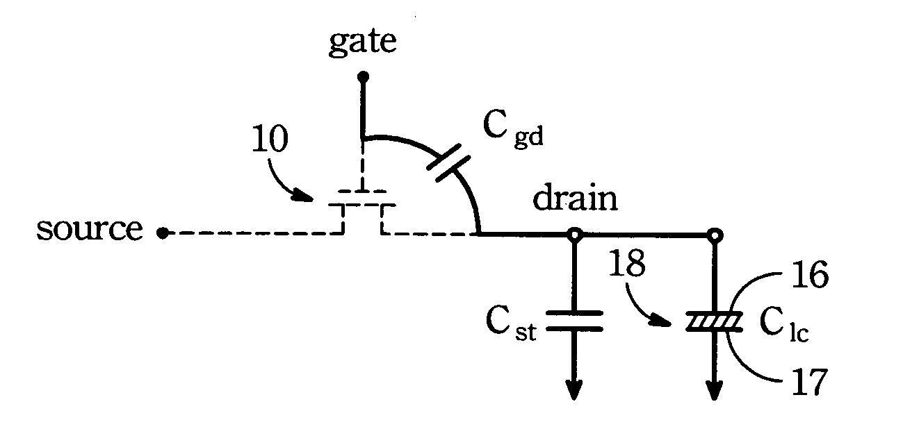
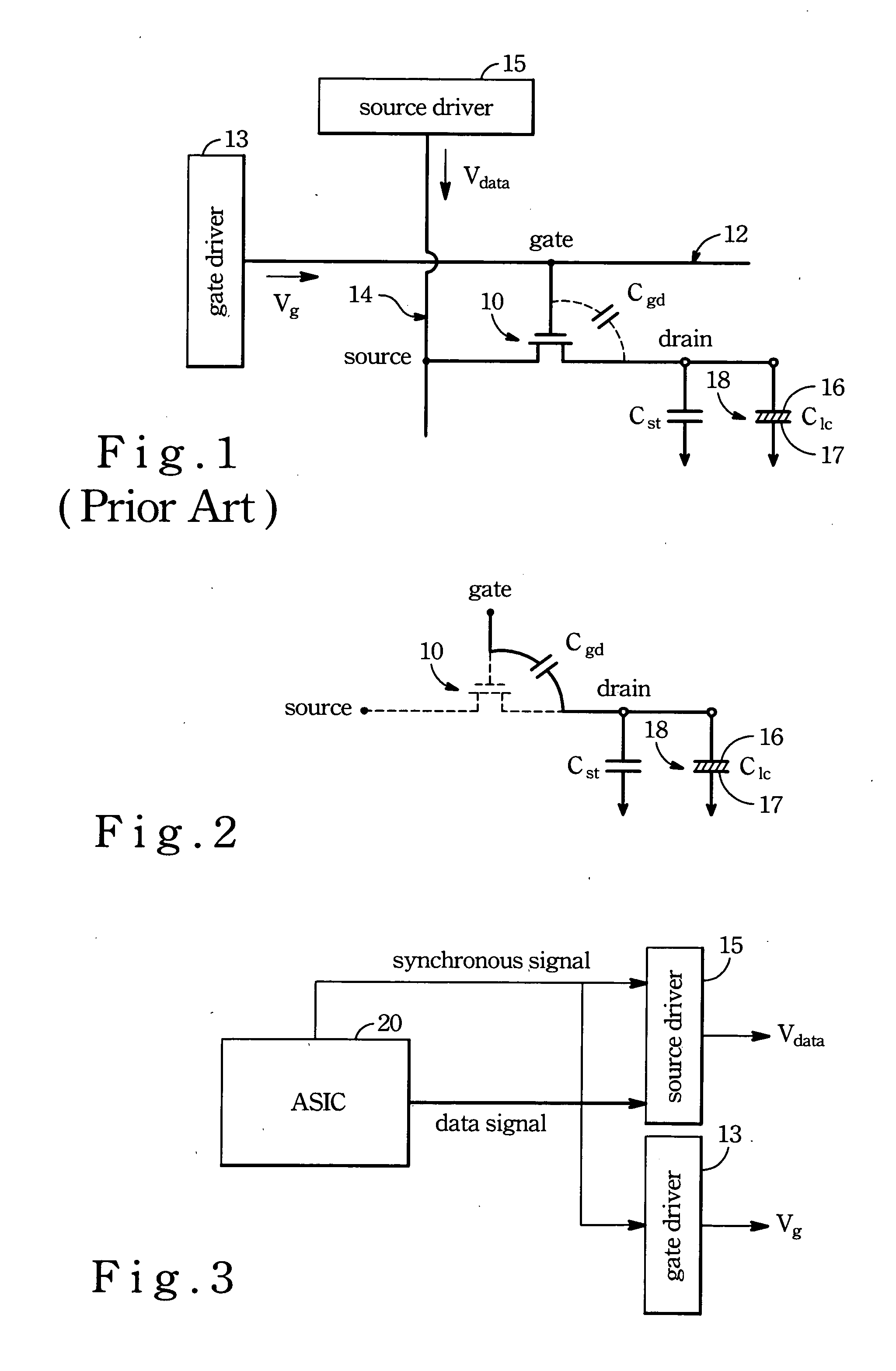
[0022] A NMOS (N-channel Metal Oxide Semiconductor) transistor 10 is used to explain the spirit of the present invention, wherein when the gate driver 13 inputs a gate signal (Vg) with a high voltage so as to switch on the transistor 10, the data signal (Vdata) inputted by the source driver 15 can be transferred to the pixel electron 16 via the source and drain of the transistor 10 so as to display an image on the screen.

[0023] Note that the voltage level of the aforesaid data signal (Vdata) is about 5 volts such that when applied onto the pixel electrode 16 can not result in quick transition of the liquid crystal molecules of the liquid crystal layer into a workable display alignment. However, the gate signal (Vg) inputted by the gate driver 1...


PUM


Abstract

A method for warming-up an LCD system which includes a pixel array having a plurality of pixel units. Each pixel unit includes a pixel electrode, and a TFT (thin film transistor) provide with a source and a gate such that a gate signal inputted into the gate can switch on and switch off the TFT so as to permit transfer of a data signal from the source to the pixel electrode. The method includes the steps: floating the source of the TFT; and applying the gate signal onto the gate which is coupled to the pixel electrode in such a manner that the pixel electrode possesses a voltage level which is substantially equal to that of the gate signal.

Description

FIELD OF THE INVENTION [0001] The present invention relates to a method for warming-up an OCB mode LCD system, more specifically to a method for applying a gate signal with a predetermined voltage level onto a gate which is coupled to a pixel electrode so as to result in quick transition of liquid crystal molecules of a liquid crystal layer from a splay alignment into a bend alignment. BACKGROUND OF THE INVENTION [0002] Advance in manufacture of TFT technology consequently brings improvement to an LCD system such that the latter can be constructed in compact size with low power consumption and lower radiation. The TFT technology is employed in manufacture of personal computers, personal digital assistances (PDA), digital watches, notebook computers, digital cameras, mobile phones, and many other consumer electronics. The manufacturers worldwide have devoted themselves to further research and thus improve the materials, processes and equipments. The qualities of the LCD system are ac...

Claims


Application Information

Patent Timeline
IPC IPC(8): G02F1/1337G02F1/1345G09G3/36H01L21/479
CPCG09G3/3648G09G2320/0252G09G2300/0491G09G3/3655
Inventor CHANG, TING-JUICHEN, PO-LUN
Owner AU OPTRONICS CORP
Why Eureka
Try Eureka