Method and application of a self adhesive splint

Inactive Publication Date: 2005-10-13
TORNAI RICHARD MANUEL
View PDF6 Cites 40 Cited by
  • Summary
  • Abstract
  • Description
  • Claims
  • Application Information

AI Technical Summary

Benefits of technology

[0009] Limited wrist movement is possible without rigid or bulky means by reducing the natural ability of the skin to stretch in the general area surrounding the wrist. This is accomplished by using a self-adhesive splint that is flexible but will not stretch. By applying the splint on top of the hand and slightly down the forearm and another strip on the palm side of the hand also extending down the forearm is an effective method of limiting unwanted wrist movement without immobilizing for two reasons. First, it can reduce overall elasticity of the skin allowing for more natural movement with better overall wrist posture. Second, the skin surrounding the perimeter of the device becomes more sensitive to movement. The enhanced sensitivity provides a biomechanical feedback in the form of a gentle tug on the skin providing a stretching sensation

Problems solved by technology

Complete restriction that is imposed on wrist movement by most existing devices is unnecessary.
Current technology restricts wrist flexion, extension ulnar, and radial movement by severely restricting and in some cases immobilizing any range of motion.
L

Method used


Image

  • Method and application of a self adhesive splint
  • Method and application of a self adhesive splint
  • Method and application of a self adhesive splint

Examples


Example

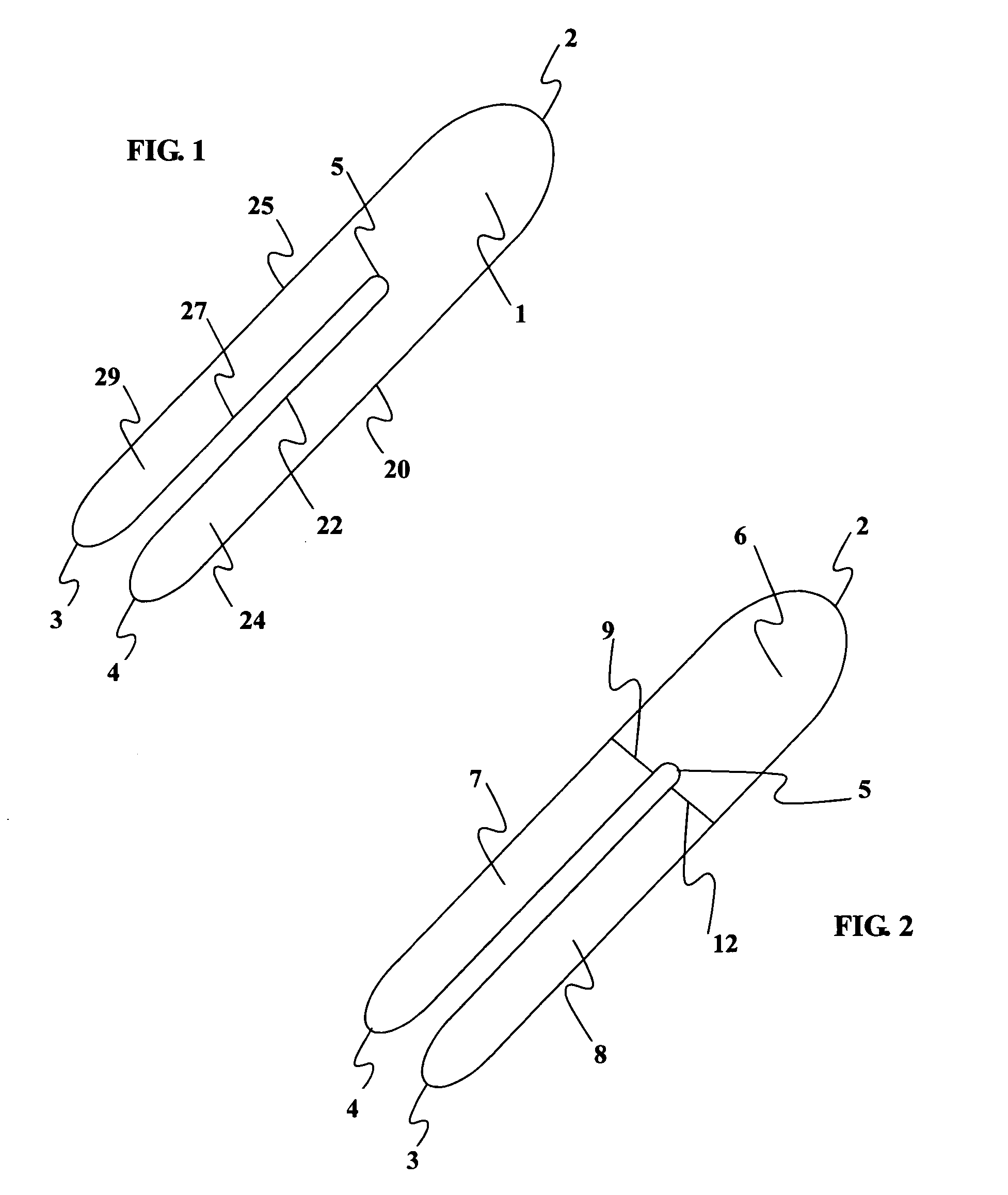
[0020] The present invention consists of a thin, non-stretch, self-adhesive splint device illustrated in FIG. 1 (top view) and method of placing the splint in such a way as to maintain proper wrist position by limiting the ability of the skin surrounding the wrist and forearm to stretch. Limiting the skin from stretching reduces hand flexion and extension movements as well as ulnar and radial deviation. The limitation of movement is accomplished by reducing skin elasticity on the skin surface area generally surrounding the wrist without applying additional pressure to the median nerve.

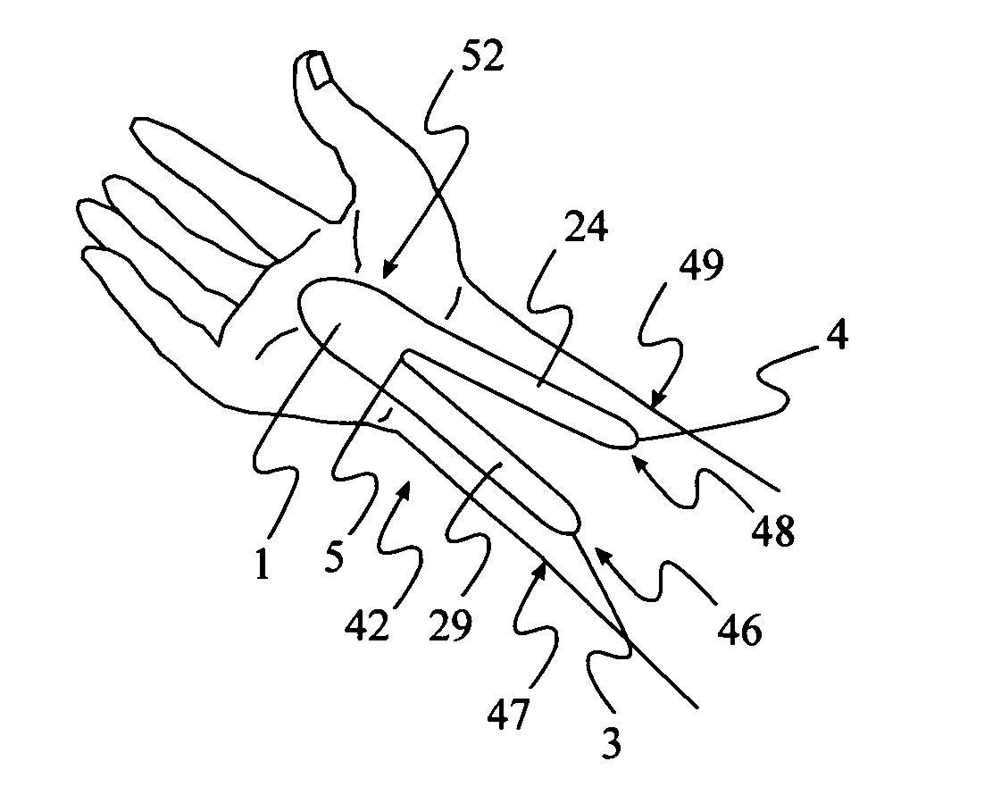
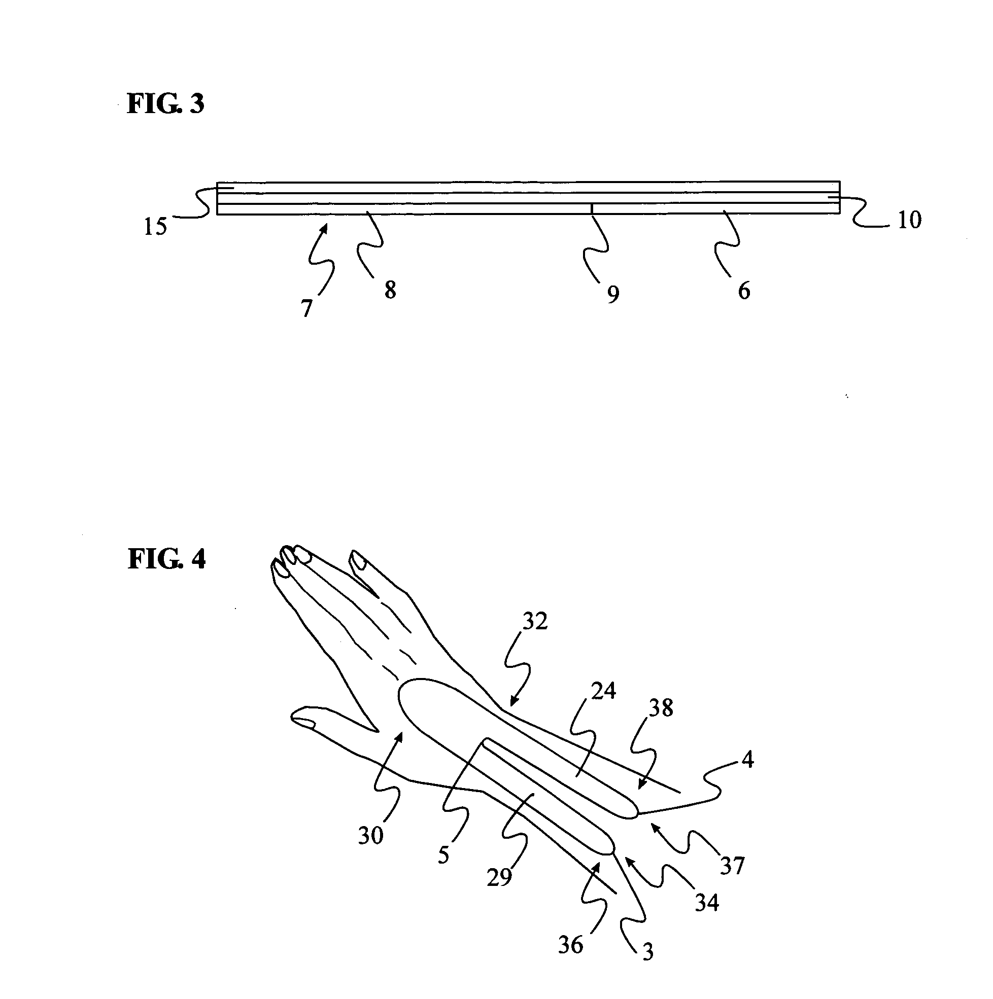
[0021] Placement of two devices, on either side of the wrist, is required to reduce both flexion and extension movement. The method of application of the device on top of the wrist FIG. 4, when in the pronated position (palm down), limits flexion. A second device properly applied on the bottom of the wrist FIG. 7, in the supinated position (palm up), limits extension. Ulnar and radial deviation moveme...


PUM


Abstract

The device is a thin, self-adhesive non-stretch splint, having the capability to flex. This device is intended for the treatment of repetitive stress injuries such as Carpal Tunnel Syndrome with elements that provide user adjustable limitation of movement within acceptable medical parameters. Carpal Tunnel Syndrome symptoms include pain and numbness in the thumb, index, and middle fingers, that are aggravated by compression of the median nerve. This device limits flexion, extension, ulnar and radial deviation movements of the wrist without compressing the median nerve The device limits movement by reducing skin elasticity on the surface skin above or below the wrist and up the forearm. The application provides biomechanical feedback to the wearer in the form of the tugging sensation on the skin around the perimeter of the device assisting the user in maintaining a more neutral wrist position without imposing wrist immobilization. The design elements allow the use of the device in such a manner that produces no additional pressure to the median nerve while in use. Furthermore the method of application provides a means for the user to regulate the amount of wrist movement to provide a greater comfort level while still limiting movement within medically proven parameters. The adhesive nature of the device eliminates the need for external straps that normally wrap completely around the forearm and hand to hold a splint in place. The application of the device limits movement by greatly reducing the ability of the skin to stretch by placing a self-adhesive non-stretch splint directly on the skin. The device, and how it is placed utilizes the wearers skin elasticity to provide biomechanical feedback to the user to promote better wrist posture.

Description

[0001] I wish to claim priority filing date of Apr. 10, 2004 from provisional application U.S. PTO Ser. No. 60 / 561239.FIELD OF THE INVENTION [0002] This invention relates to the use of rigid and semi rigid splints for the treatment and prevention of repetitive stress injuries specifically Carpal Tunnel Syndrome. DESCRIPTION OF THE PRIOR ART [0003] Rigid and semi rigid splints are commonly used in the treatment of repetitive stress injuries. Carpal Tunnel Syndrome (CTS) is categorized as a repetitive stress injury. CTS is caused due to compression of the median nerve located under the transverse carpal ligament in the center of the wrist in a small channel called the Carpal Tunnel. Repetitive movement and poor wrist posture can cause the tissue around the median nerve to swell thereby compressing it. The symptoms usually consist of pain and numbness in the thumb, index, and middle fingers. [0004] Repetitive stress injuries such as CTS can be easily aggravated by flexing or extending ...

Claims


Application Information

Patent Timeline
IPC IPC(8): A61F5/00A61F5/01
CPCA61F5/0118
Inventor TORNAI, RICHARD MANUEL
Owner TORNAI RICHARD MANUEL
Why Eureka
Try Eureka