Vehicle control system and method

a technology of vehicle control system and control architecture, applied in the direction of braking system, process and machine control, instruments, etc., can solve the problems of inability to control, control architecture does not provide significant redundancy or fault tolerance with respect, and control architecture does not provide significant redundancy or fault tolerance, so as to improve reduce the need for voting, and improve the effect of fault tolerance and redundancy

Active Publication Date: 2005-10-13
GM GLOBAL TECH OPERATIONS LLC
View PDF8 Cites 47 Cited by
  • Summary
  • Abstract
  • Description
  • Claims
  • Application Information

AI Technical Summary

Benefits of technology

[0008] The control system is generally adapted to provide control using the processed sensor signals. However, the control system is adapted to use the unprocessed sensor signals to provide redundancy and fault tolerance with regard to the processed sensor signals. The invention also includes a method in which each of the controllers compares the processed sensor signal(s) and the unprocessed sensor signal(s) it has received to determine a signal differential. The signal differentials are compared against a predetermined differential threshold to identify potential faults associated with the processed or unprocessed sensor signals. If no fault is detected, the processed sensor signal is used by the controllers to provide control based on the sensed input. If a fault is identified, the controllers are adapted to vote to determine a resolved sensor signal. The resolved sensor signal may include an average or median value of the signals not associated with the fault, or may include a predetermined fault value if the voting is not able to determine a reliable value of the sensor signal for use in control. The sensor status signal may also be utilized to provide an additional measure of fault tolerance and reduce the need for voting between the controllers to determine the resolved sensor signal in the event of a fault.
[0009] The present invention is advantageous in that it provides improved fault tolerance and redundancy over related art systems which utilize unprocessed sensor signals and continuous voting through the controller bus to determine a control signal because it is believed to be less susceptible to events related to the controller bus, since voting over the controller bus is only required if a signal fault is detected. The present invention is also advantageous in that it provides improved fault tolerance and redundancy over prior art systems which utilize processed sensor signals because it is believed to be more fault tolerant with respect to events related to the control modules or loss of the processed signal to one or more of the controllers, since voting using the unprocessed sensor signals may be utilized to determine a resolved sensor signal in response to such events.

Problems solved by technology

However, such systems also typically remove any direct mechanical or hydraulic force transmitting path between the vehicle operator and the controller.
However, this control architecture does not provide significant redundancy or fault tolerance with respect to a single point event related to controller bus 218 because such an event may make it impossible for controllers 212,214,216 to vote to determine the representative steering, accelerator and braking sensor signal to be used for control of these systems.
However, this control architecture does not provide significant redundancy or fault tolerance with respect to a single point event related to one of the signal processing modules, because such an event may affect the processed sensor signal associated with the module in which the event occurs, thus making it impossible for controllers 312,314,316 to provide vehicle control associated with such signal.
Also, if voting is utilized, this architecture does not provide significant redundancy or fault tolerance with respect to a single point event related to the controller bus, as described above.

Method used


Image

  • Vehicle control system and method
  • Vehicle control system and method
  • Vehicle control system and method

Examples


Embodiment Construction

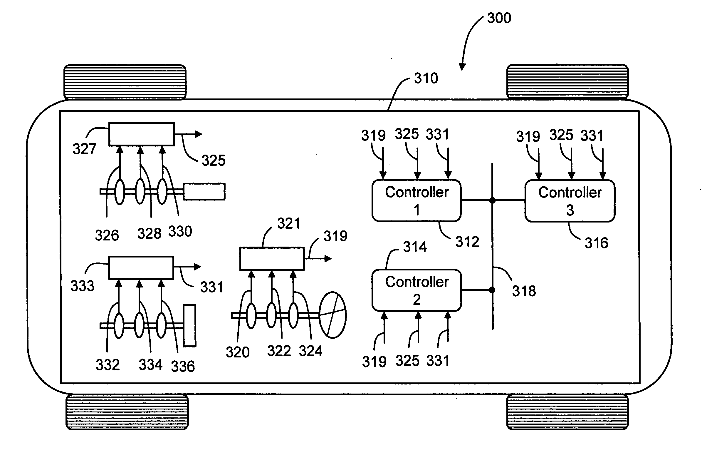
[0019]FIG. 3 schematically illustrates a vehicle 400 having vehicle control system 410. A configuration such as that illustrated for vehicle control system 410 would be applicable to a vehicle 400 having a plurality of by-wire control systems, such as by-wire steering control, accelerator control and braking control systems. Vehicle control system 410 comprises three vehicle or system controllers to provide the desired redundancy associated with the control of vehicle 400, and includes first controller 412, second controller 414 and third controller 416. Controllers 412,414,416 are each operatively connected to controller bus 418 and are each in signal communication with one another through controller bus 418, such that any information or input received by one of the controllers may be shared with any or all of the other controllers. Controllers 412,414,416 are each adapted to receive both unprocessed (raw) sensor signals as well as a processed sensor signal associated with at least...


PUM


Abstract

A control system and method for use in vehicles, such as automotive vehicles. The control system and method is particularly adapted for use in vehicles having by-wire control systems. The control system uses three system controllers. Each of the controllers is adapted to receive redundant control inputs from at least one input device, such as a steering actuator, an accelerator actuator and a brake actuator. Each controller is adapted to receive a different unprocessed actuator sensor signal and a processed actuator sensor signal which are associated with the input device. Each controller may also be adapted to receive a sensor status signal which is also associated with the input device. In accordance with the method of the invention, these signals may be used to determine a sensor signal which may be used as the basis for control of control systems or components in response to the input device. Depending on the status of these signals, the sensor signal used for control may comprise the processed sensor signal or a resolved sensor signal. The sensor signal used for control may be determined by implementing a voting process in conjunction with the controllers which utilizes both the unprocessed sensor signals and the processed sensor signals.

Description

TECHNICAL FIELD [0001] This invention generally comprises a vehicle control system. More particularly, this invention comprises a fault tolerant by-wire vehicle control system. BACKGROUND OF THE INVENTION [0002] By wire vehicle control systems provide a number of advantages with regard to system packaging. The associated electronic control systems and the implementation of advanced computer control algorithms facilitate a number of new control features. However, such systems also typically remove any direct mechanical or hydraulic force transmitting path between the vehicle operator and the controller. Therefore, much attention has been given to designing by wire vehicle control systems and control architectures that ensure their operability in response to an event (e.g., any event which negatively impacts or affects control signals, data, hardware, software or other elements associated with the operation of such systems) occurring in the control path between the control command ini...

Claims


Application Information

Patent Timeline
Patent Type & Authority Applications(United States)
IPC IPC(8): B60T8/00B60T8/88B60W50/02B62D5/00B62D6/00G06F17/00
CPCB60T8/885B62D5/001B60W50/023B60T2270/413
Inventor NAIK, SANJEEV M.MISHRA, PRADYUMNA K.HOWELL, MARK N.DEBOUK, RAMI I.SALMAN, MUTASIM A.
Owner GM GLOBAL TECH OPERATIONS LLC
Why Eureka
Try Eureka