Transmitting device and transmitting method

a transmission device and transmission method technology, applied in the direction of code conversion, code correction/detection using turbo codes, code conversion, etc., can solve the problems of reducing the number of user signals that can be multiplexed, reducing frequency utilization efficiency, and improving error rate characteristics, so as to achieve mutually more compatible error rate characteristics and transmission efficiency

Inactive Publication Date: 2005-10-13
PANASONIC INTELLECTUAL PROPERTY CORP OF AMERICA
View PDF23 Cites 25 Cited by
  • Summary
  • Abstract
  • Description
  • Claims
  • Application Information

AI Technical Summary

Benefits of technology

[0009] It is an object of the present invention to provide a transmission apparatus and transmission method c

Problems solved by technology

However, the conventional CDMA transmission apparatus has a problem that when a plurality of spread signals is assigned to one user signal for spreading to improve its error rate characteristic, the number of user signals that can be multiplexed is reduced, and therefore the frequency utilization efficiency is reduced and wh

Method used


Image

  • Transmitting device and transmitting method
  • Transmitting device and transmitting method
  • Transmitting device and transmitting method

Examples


embodiment 1

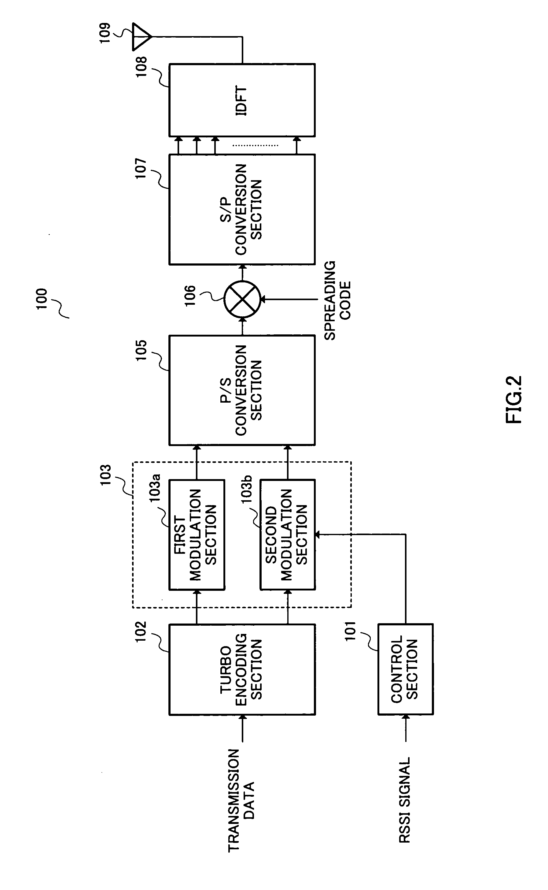
[0025]FIG. 2 illustrates a configuration of a transmission apparatus 100 according to Embodiment 1 of the present invention. Here, Embodiment 1 will describe a case where two kinds of modulation schemes, QPSK and 16 QAM are used. Furthermore, the modulation scheme with more multi-values according to Embodiment 1 is 16 QAM and the modulation scheme with fewer multi-values is QPSK.

[0026] The transmission apparatus 100 is mainly constructed of a control section 101, a turbo encoding section 102, a modulation section 103, a P / S conversion section 105, a spreader 106, a serial / parallel (hereinafter referred to as “S / P”) conversion section 107, an inverse discrete Fourier transform section (IDFT) 108 and an antenna 109. Furthermore, the modulation section 103 is mainly constructed of a first modulation section 103a and a second modulation section 103b.

[0027] The control section 101 decides communication quality using an RSSI (Received Signal Strength Indicator) signal, and outputs a con...

embodiment 2

[0046]FIG. 5 illustrates a configuration of a transmission apparatus 400 according to Embodiment 2 of the present invention. Here, this Embodiment 2 will describe a case where two types of modulation schemes; QPSK and 16 QAM are used. Furthermore, in this Embodiment 2, the modulation scheme with more multi-values is 16 QAM and the modulation scheme with fewer multi-values is QPSK.

[0047] A modulation section 402 in this Embodiment 2 is mainly constructed of a first modulation section 402a and a second modulation section 402b. This Embodiment 2 is characterized in that the modulation schemes in both the first modulation section 402a and second modulation section 402b are adaptively modulated according to communication quality. Note that this embodiment is different from FIG. 2 in that a control signal from the control section 401 is input to the first modulation section 402a, and explanations of the same components as those in Embodiment 1 will be omitted.

[0048] The control section ...

embodiment 3

[0063]FIG. 8 illustrates a configuration of a transmission apparatus 700 according to Embodiment 3 of the present invention. Here, when two types of modulation schemes QPSK and 16 QAM are used in Embodiment 3, a case where QPSK is used as a modulation scheme with fewer multi-values will be explained. In this Embodiment 3, the modulation scheme with more multi-values is 16 QAM and the modulation scheme with fewer multi-values is QPSK.

[0064] This Embodiment 3 is characterized in that while transmission data (other data) for which good reception quality is not required is modulated according to 16 QAM with more multi-values, when transmitting transmission data for which good reception quality is required, the modulation schemes for both the first modulation section 103a and second modulation section 103b are always set to QPSK which is a modulation scheme with fewer multi-values. Here, the same components as those in FIG. 2 are assigned the same reference numerals and explanations the...


PUM


Abstract

A turbo encoding section 102 turbo-encodes transmission data, outputs systematic bit data to a first modulation section 103a and outputs parity bit data to a second modulation section 104. The first modulation section 103a always QPSK-modulates systematic bit data. The second modulation section 103b adaptively modulates parity bit data. The control section 101 outputs a control signal for carrying out 16 QAM modulation to the second modulation section 103b when the RSSI value is equal to or higher than a threshold and outputs a control signal for carrying out QPSK modulation to the second modulation section 103b when the RSSI signal value is less than the threshold. In this way, it is possible to further make the error rate characteristic compatible with the transmission efficiency.

Description

TECHNICAL FIELD [0001] The present invention relates to a transmission apparatus and transmission method, and more particularly, to a transmission apparatus and transmission method for transmitting transmission data encoded using a turbo encoder. BACKGROUND ART [0002] Conventionally, a turbo code is available as an error correcting / encoding scheme and used by the 3GPP for standardization. Compared to other error correcting schemes, this turbo code is characterized by its ability to obtain an error rate characteristic of extremely high quality. [0003] An example of a transmission apparatus using a conventional turbo code is shown in FIG. 1. The transmission apparatus 10 shown in FIG. 1 is provided with a turbo encoding section 11, a parallel / serial (hereinafter referred to as “P / S”) conversion section 12, a spreading section 13, a radio transmission section 14 and an antenna 15. [0004] A turbo encoding section 11 receives a transmission signal, converts the signal to a turbo code, ge...

Claims


Application Information

Patent Timeline
IPC IPC(8): H03M13/25H03M13/29H04L1/00H04L1/18H04L5/02H04L27/00
CPCH03M13/25H03M13/256H03M13/258H03M13/2957H04L27/36H04L1/0066H04L1/1893H04L27/206H04L27/2602H04L1/0004
Inventor SUDO, HIROAKI
Owner PANASONIC INTELLECTUAL PROPERTY CORP OF AMERICA
Why Eureka
Try Eureka