System and method for low-delay channel hopping

a channel hopping and low-delay technology, applied in the field of image and video compression coding, can solve the problems of dependency, delay is very annoying to a viewer, and significant delay occurs before the new channel is buffered, so as to reduce the delay in changing channels and reduce the delay

Inactive Publication Date: 2005-10-13
SHARP LAB OF AMERICA INC
View PDF13 Cites 66 Cited by
  • Summary
  • Abstract
  • Description
  • Claims
  • Application Information

AI Technical Summary

Benefits of technology

[0015] To address the delay associated with changing channels, the present invention buffers compressed data from one or more channel(s) not currently being decoded, in anticipation of a change to one of the buffered channel. When a channel change is initiated, the decoder locates an access point, such as an I-frame held in the buffer, and immediately begins decoding, starting at the location of the most recently received I-frame. This invention defines how data is buffered and how a decoder accesses this buffered data in response to a channel change. The present invention significantly reduces the delay in chan

Problems solved by technology

When a decoder receiving one channel, switches to another channel, a significant delay occurs before the new channel is buffered, decoded and played back.
This delay is very annoying to a viewer, especially a channel surfer.
The data dependency introduces a time delay responsive to the frequency of I-frames in the data.
A second source of

Method used


Image

  • System and method for low-delay channel hopping
  • System and method for low-delay channel hopping
  • System and method for low-delay channel hopping

Examples


Embodiment Construction

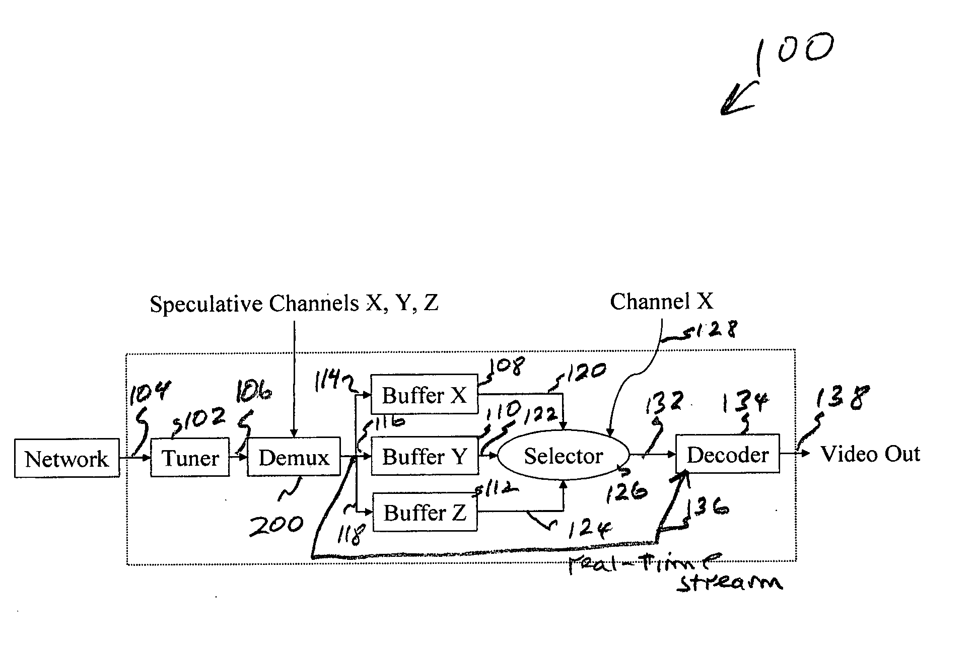
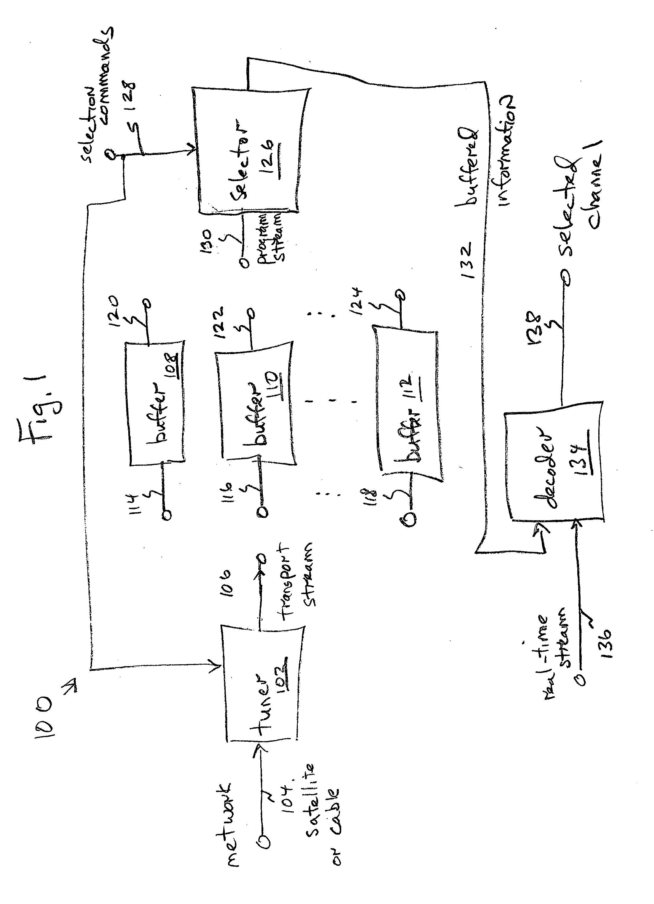
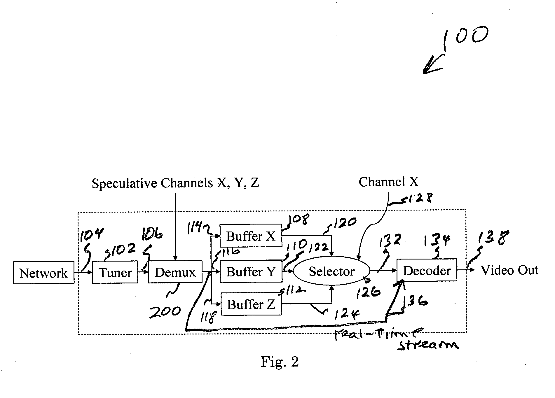
[0027]FIG. 1 is a schematic block diagram of the present invention system for low-delay channel changes. The system 100 comprises a tuner 102 having a network interface on line 104 to receive a multicast / broadcast with a plurality of compressed video channels and an interface on line 106 to supply transport streams. The line 104 may represent a digital TV cable or satellite video interface, for example, to receive compressed video channels in a format such as MPEG-1, MPEG-2, MPEG-4, H.261, H.263, or H.264. However, the system has application to any compressed video format that uses predictive frames in the encoding / decoding process. In some aspects, line 104 may be connected to multiple sources, or selectively connected to different sources. For example, line 104 may simultaneously supply compressed video information from both a satellite and cable source, or from two different cable sources.

[0028] The system includes a plurality of buffers. Shown are three buffers, buffer 108 thro...


PUM


Abstract

A system and method are provided for low-delay channel changes in a multicast/broadcast of compressed video. The method comprises: receiving a multicast/broadcast with a plurality of compressed video channels; buffering information from a plurality of channels; selecting a channel; and, decoding the selected channel in response to the buffered information. In some aspects, the method pre-identifies access points in the buffered information for each channel, prior to selecting the channel. Then, decoding the selected channel in response to the buffered information includes: accessing the buffered information at the pre-identified access point; and, decoding the selected channel, beginning at the access point. Alternately, access points are not pre-identified. Then, decoding the selected channel in response to the buffered information includes: discovering an access point in the information buffered for the selected channel subsequent to selecting the channel; and, decoding the selected channel, beginning at the discovered access point.

Description

BACKGROUND OF THE INVENTION [0001] 1. Field of the Invention [0002] This invention generally relates to image and video compression coding and, more particularly, to a system and method for minimizing the delay associated with decoded video channels after a specific channel is selected. [0003] 2. Description of the Related Art [0004] This invention addresses the problem of channel change in the broadcast or multicast streaming of compressed digital video. When a decoder receiving one channel, switches to another channel, a significant delay occurs before the new channel is buffered, decoded and played back. This delay is very annoying to a viewer, especially a channel surfer. To understand the behavior of a typical digital decoder during a channel change, the main sources of channel changing delay must be understood. [0005] Digital video compression, such a motion pictures expert group (MPEP)-1, MPEG-2, MPEG-4 H.261, H.263, and H.264, exploit temporal correlation between frames. A f...

Claims


Application Information

Patent Timeline
IPC IPC(8): H04N5/00H04N7/16H04N7/173
CPCH04N21/42607H04N21/44222H04N21/4385H04N21/4331
Inventor KEROFSKY, LOUIS JOSEPHLEI, SHAWMIN
Owner SHARP LAB OF AMERICA INC
Why Eureka
Try Eureka