
Electromagnetic flanging and hemming apparatus and method

a technology of heming apparatus and heming wire, which is applied in the field of heming apparatus and methods of electromagnetic heming wire, can solve the problems of cracking failure and very high strain rate deformation, and achieve the effects of enhancing ductility of metals, enhancing ductility, and great bending plasticity

Inactive Publication Date: 2005-10-20
RES IN MOTION LTD +1
View PDF6 Cites 20 Cited by
  • Summary
  • Abstract
  • Description
  • Claims
  • Application Information

AI Technical Summary

Benefits of technology

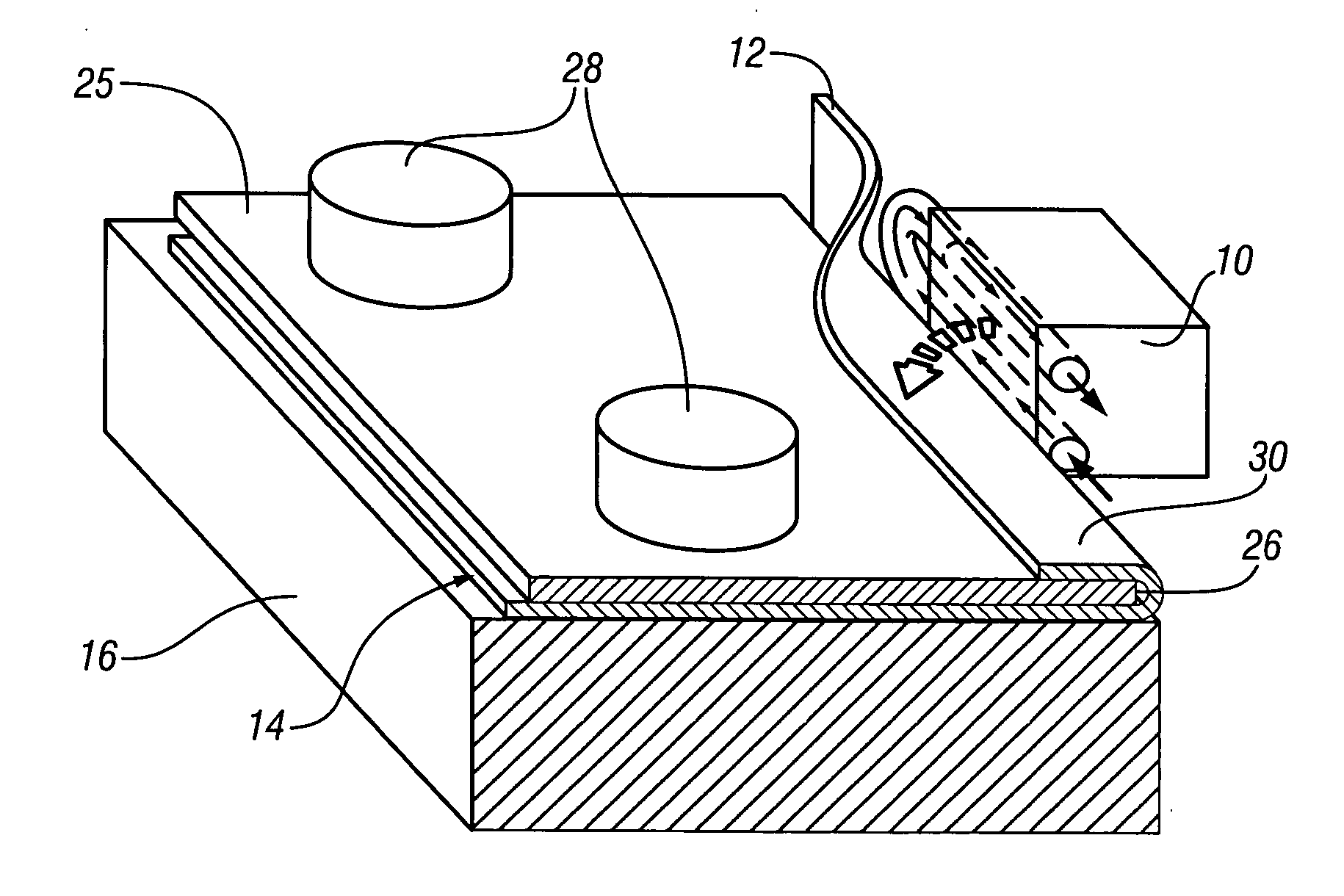
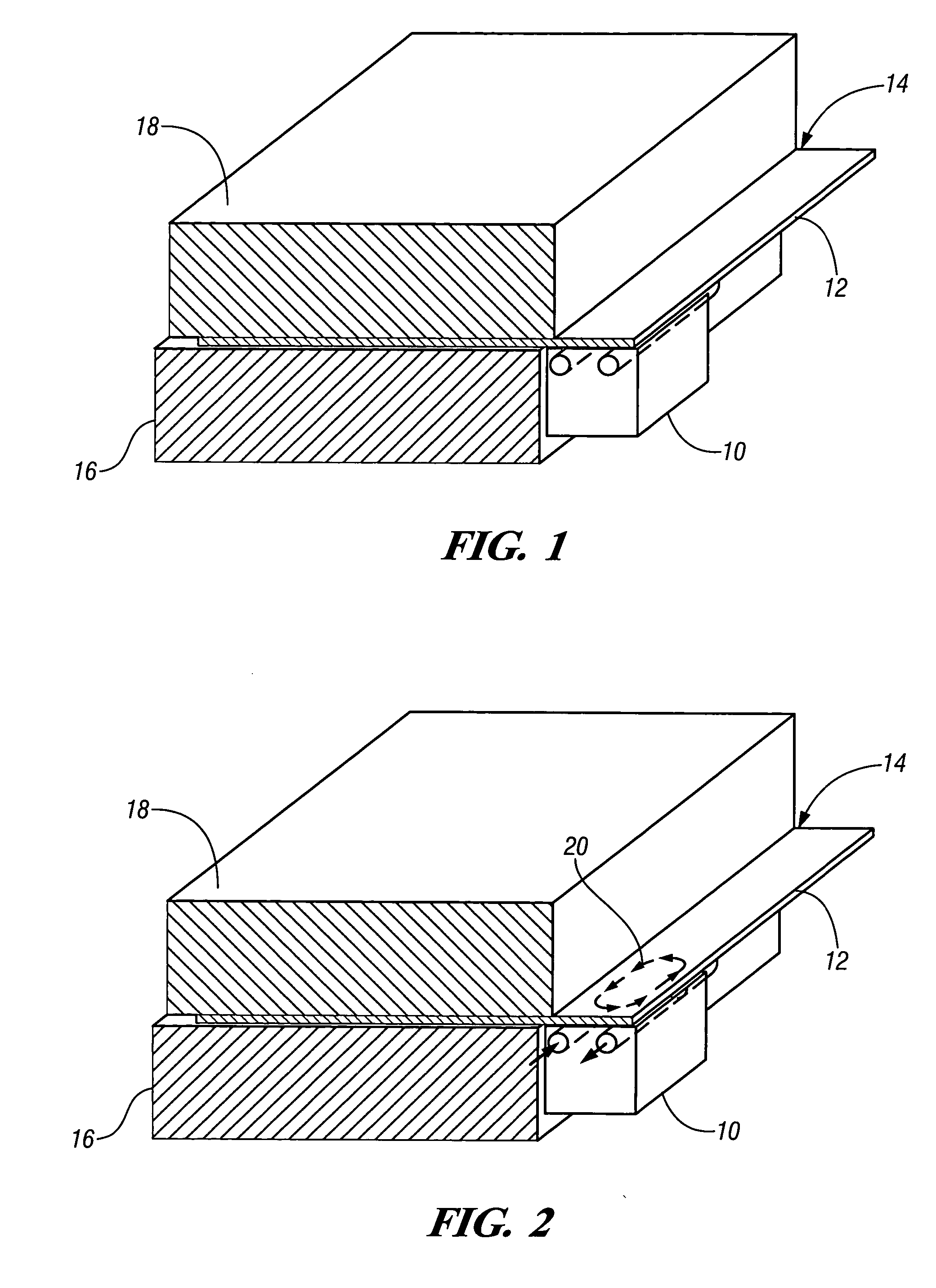
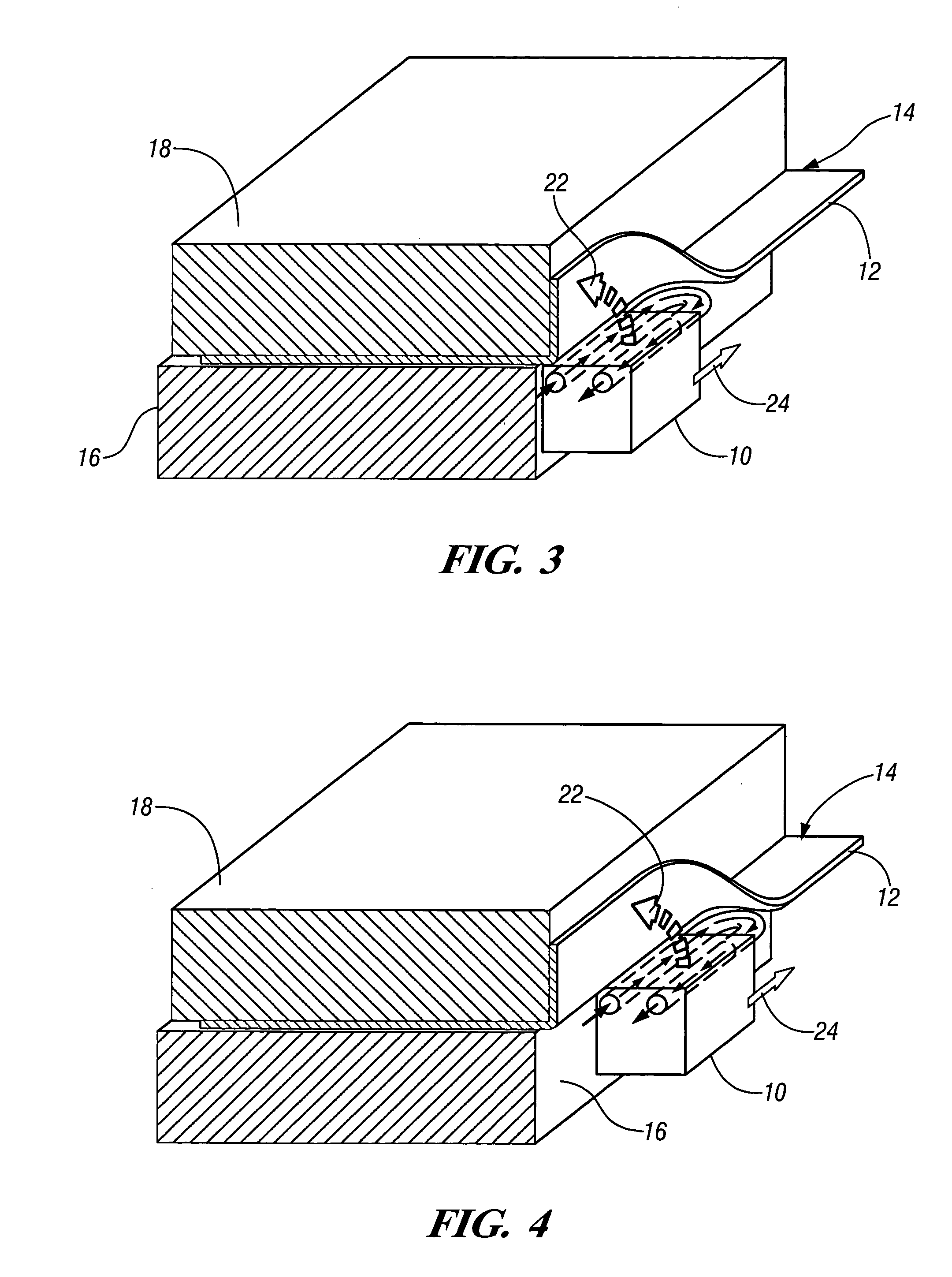
[0007] In this invention, the solid roller of the roller hemming concept is replaced with an electromagnetic coil designed to force the sheet metal flange to bend around the hemline to the closed hem position. A robot, or other device, can drive the electromagnetic coil with translation and rotation around the part contour as required. The combined advantages of non-plane strain bending and hyperplasticity may be realized to avoid cracking failure in aluminum panels.
[0013] Non-plane strain bending—the alternate strain path enables greater bending plasticity to avoid cracking in AA6111 aluminum panels.
[0014] Improved hem quality—electromagnetic (EMF) forming enhances the ductility of metals, which can enable greater bending strains and sharper hems to attain the “jewel” effect at the hemline.
[0015] Elimination of the conventional flanging process—EMF may be used to flange and hem panels from 180° open to the closed, flat hem condition. The hold-down fixture of the inner panel could be used to provide the support needed to establish the break line of the hem. Alternatively, the outer edge of the inner panel could also be used to wrap the outer flange around the inner panel, creating a tight, flat, crisp hem appearance.

Problems solved by technology

With the coil held in a fixed position, the repulsive magnetic forces act upon the workpiece causing it to deform at very high strain rates.
Conventional hemmers deform the flange through a “plane strain bending” path, which is very severe and can cause cracking failure when hemming aluminum panels, especially panels stamped from AA6111.

Method used


Image

  • Electromagnetic flanging and hemming apparatus and method
  • Electromagnetic flanging and hemming apparatus and method
  • Electromagnetic flanging and hemming apparatus and method

Examples


Embodiment Construction

[0021] Manufacture of hemmed panel assemblies commonly involves a series of manufacturing steps, including forming, flanging and hemming. The hemming process begins with individual metal sheets that are cut, surface treated as desired and formed by known processes, such as by drawing or stamping, into three dimensional panels ready to be assembled into a panel assembly. These steps do not form part of the apparatus and method of the present invention, although they may be combined with this invention to form a hemmed panel manufacturing process.

[0022] This invention is directed to apparatus and methods used in flanging and / or hemming steps involving electromagnetic forming of hemmed panel assemblies. The following exemplary embodiments and steps incorporate various related concepts of flexible EMF flanging and hemming, as shown in the drawings.

Outer Panel Flanging

[0023] An initial step directed to electromagnetic (EMF) flanging of an outer panel for hemming is illustrated in FIG...


PUM

PropertyMeasurementUnit
Lengthaaaaaaaaaa
Magnetic fieldaaaaaaaaaa
Electromagnetic forceaaaaaaaaaa

Abstract

Apparatus and methods are disclosed for applying electromagnetic force (EMF) to flanging and hemming metal panels to form a hemmed panel assembly. First and second apparatus and method steps use a translating EMF coil to flange a sheet and to finish a hem by progressive non-planar bending. An alternate embodiment uses EMF hemming for difficult-to-hem portions of a flange and optionally precedes this with conventional hemming of straight hem portions.

Description

CROSS REFERENCE TO RELATED APPLICATIONS [0001] This application claims priority from U.S. Provisional Patent Application No. 60 / 562,853 filed Apr. 15, 2004.TECHNICAL FIELD [0002] This invention relates to hemming the edges of inner and outer body panels to form a hemmed assembly having closed edges and to flanging of outer panels prior to hemming. More particularly, the invention relates to electromagnetic (EMF) flanging and hemming apparatus and methods. BACKGROUND OF THE INVENTION [0003] Electromagnetic (EMF) forming uses very high-current pulses in a specially designed electrical coil to generate magnetic fields, which impart opposing magnetic fields in a highly electrically conductive metal workpiece, such as an aluminum alloy or steel. With the coil held in a fixed position, the repulsive magnetic forces act upon the workpiece causing it to deform at very high strain rates. Metals deformed at these very high strain rates can exhibit “hyperplasticity,” a level of plastic ductili...

Claims


Application Information

Patent Timeline
IPC IPC(8): B21D5/16B21D17/02B21D26/14B21D39/02B23P11/00
CPCB21D39/021Y10T29/49915Y10T29/53065Y10T29/49803Y10T29/49908
Inventor BRADLEY, JOHN R.CARSLEY, JOHN E.
Owner RES IN MOTION LTD
Learn More