Non-tracheal ventilation tube

a ventilation tube and non-tracheal technology, applied in the field of non-tracheal ventilation tubes, can solve the problems of insufficient respiratory gases reaching the patient, irritating the patient, and difficult breathing of patients spontaneously, so as to reduce the outside diameter of the tube shaft, reduce the lifting of the larynx of the patient, and reduce the effect of the tube diameter

Active Publication Date: 2005-10-20
KING SYST
View PDF37 Cites 46 Cited by
  • Summary
  • Abstract
  • Description
  • Claims
  • Application Information

AI Technical Summary

Benefits of technology

[0012] One feature of the present invention is that the ventilation channel ends between the proximal and distal cuffs allowing the outside diameter of the tube shaft to be reduced at the distal cuff. This reduces the diameter of the non-tracheal ventilation tube that is inserted into the entrance of the esophagus of the patient which means less lifting of the larynx of the patient than would be required if the ventilation channel extended through the distal cuff which reduces the discomfort to the patient.
[0013] Another feature of the present invention is that the distal cuff can have an oval or elliptical shaped cross-section with the major axis extending laterally and the minor axis being in the anterior-posterior direction of the ventilation tube. The inflated elliptical-shaped distal cuff provides a gas and liquid tight seal at the entrance of the esophagus while avoiding unnecessary lifting of the larynx at the entrance to the esophagus. This more closely fits the anatomy of the patient which provides greater patient comfort and reduces recovery time.
[0014] Yet another feature of the present invention is that the suction channel has a generally circular or oval cross-section which has several advantages over a semi-circular or other cross-section having corners. The generally circular cross-section permits easy insertion and passage of a suction tube with a generally circular cross section of smaller outside diameter through the suction channel.
[0015] The generally circular cross-section also allows better utilization of the inside diamet

Problems solved by technology

However, the extent and circumference of the aforementioned tubes can cause irritation to the patient, especially at the entrance of the esophagus.
The patient's epiglottis or other laryngeal tissue can cause bloc

Method used


Image

  • Non-tracheal ventilation tube
  • Non-tracheal ventilation tube
  • Non-tracheal ventilation tube

Examples


Embodiment Construction

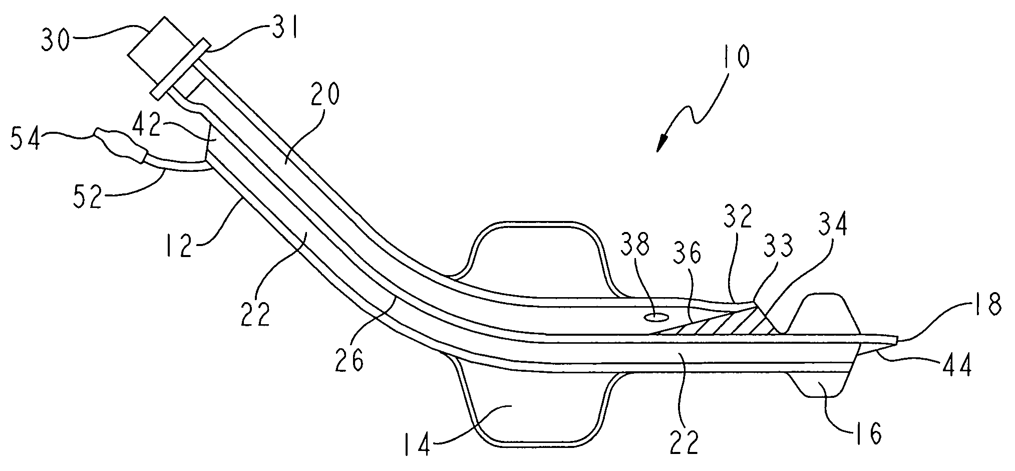
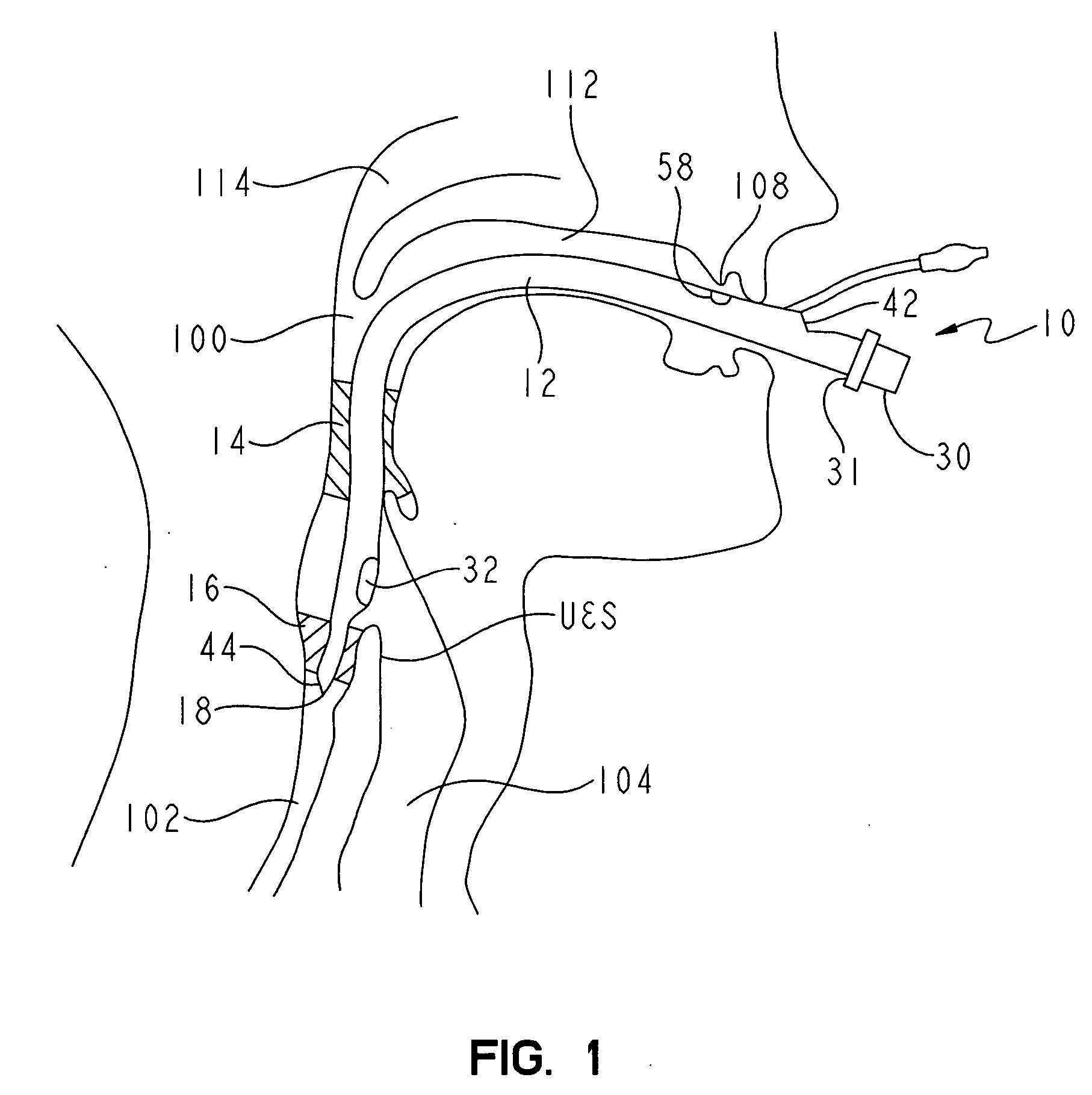
[0035]FIG. 1 shows a non-tracheal ventilation tube 10 inserted into the airway 100 and extending into the esophagus 102 of a patient. The non-tracheal ventilation tube 10 comprises a multi-lumen tube shaft 12 having a distal end 18; and attached to the tube shaft 12 are an inflatable proximal cuff 14 and an inflatable distal cuff 16. The non-tracheal ventilation tube 10 preferably has an S-shaped longitudinal profile to help ensure that the distal end 18 of the non-tracheal ventilation tube 10 is introduced into the esophagus 102 and not into the trachea 104. The distal end 18 of the non-tracheal ventilation tube 10 is preferably made of a soft and flexible material for greater patient comfort. When properly introduced into the airway 100 of the patient, the inflated proximal cuff 14 blocks the trachea 104 from the nasopharynx 114 and the oropharynx 112, and the inflated distal cuff 16 blocks the trachea 104 from the esophagus 102.

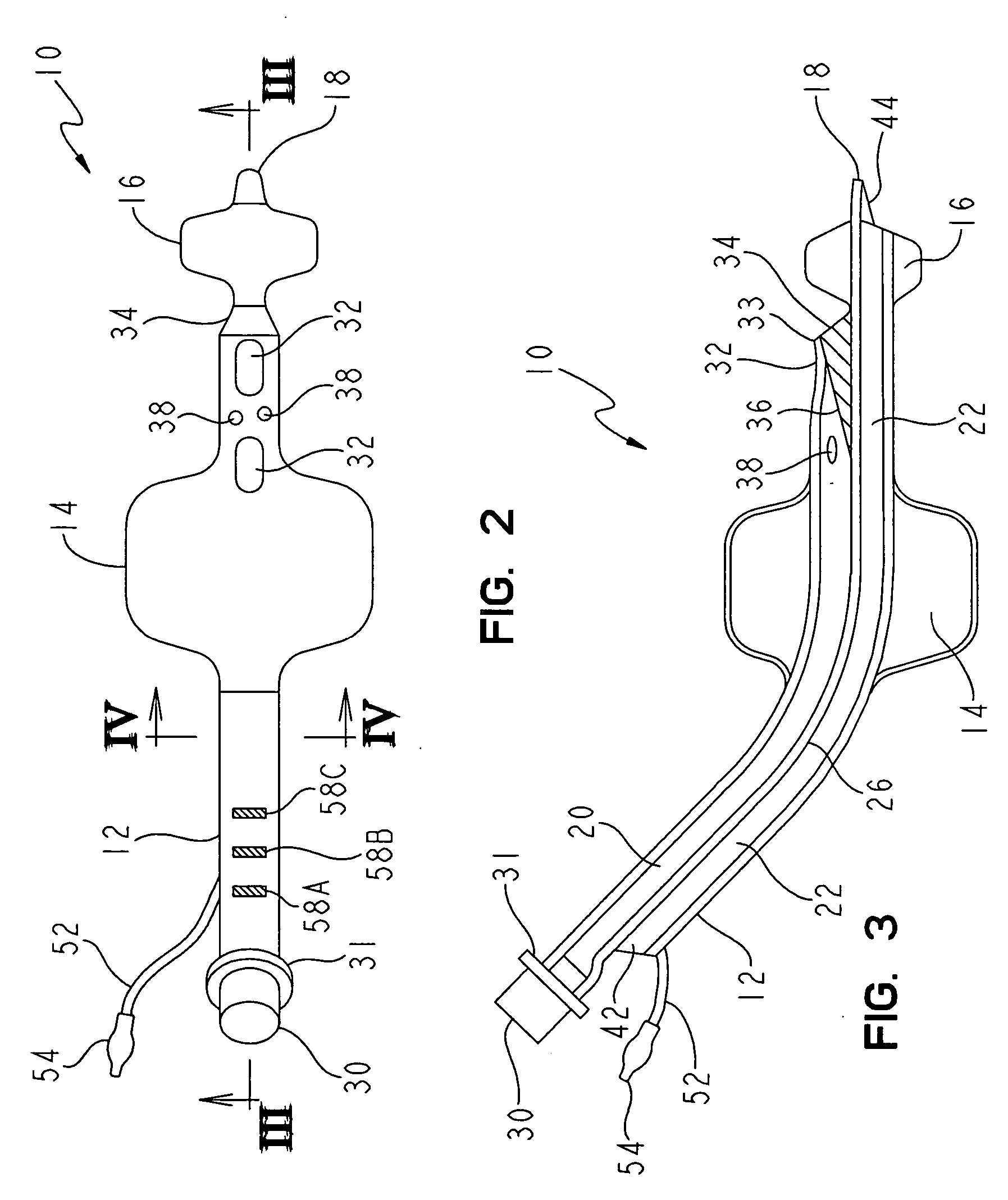
[0036]FIG. 2 shows a top-view of one embodiment of ...


PUM


Abstract

A non-tracheal ventilation tube includes a multi-lumen tube shaft having a proximal end and a distal end, a proximal cuff and a distal cuff. The multi-lumen tube shaft is separated into a ventilation channel extending from a proximal ventilation opening to a distal ventilation opening, a suction channel extending from a proximal suction opening to a distal suction opening, and an inflation channel. The proximal cuff is attached to the tube shaft and is connected to the inflation channel for inflation and deflation. The distal cuff is attached to the tube shaft on the distal side of the proximal cuff and is connected to the inflation channel for inflation and deflation. The proximal suction opening and the proximal ventilation opening are located on the proximal side of the proximal cuff. The distal suction opening is located on the distal side of the distal cuff. The distal ventilation opening is located between the proximal cuff and the distal cuff. The outside diameter of the tube shaft decreases between the proximal cuff and the distal cuff due to the ending of the ventilation channel.

Description

I. CLAIM OF PRIORITY [0001] This application claims priority to Thomas W. McGrail U.S. Provisional Application No. 60 / 562,169 which was filed on 14 Apr. 2004TECHNICAL FIELD OF THE INVENTION [0002] The present invention relates to a non-tracheal ventilation tube, and in particular, to a non-tracheal ventilation tube for anesthesia or resuscitation comprising an inflatable proximal cuff for blocking the pharynx, an inflatable distal cuff for blocking the entrance to the esophagus, and a multi-lumen tube shaft providing separate channels with access to the trachea and the esophagus. III. BACKGROUND OF THE INVENTION [0003] A multi-lumen non-tracheal ventilation tube having two inflatable cuffs and an application opening disposed between the cuffs has become well known in the art. These devices are used in emergency resuscitations, application of anesthesia in operating theaters, and other situations requiring artificial respiration of a patient, or controlled access to the trachea and / o...

Claims


Application Information

Patent Timeline
IPC IPC(8): A61M16/00A61M16/04A62B9/06
CPCA61M16/04A61M16/0434A61M16/0463A61M16/0409A61M16/0486A61M16/0459A61M16/0479A61M16/0484A61M16/0415A61M2016/0027A61M16/042A61M16/0445
Inventor MCGRAIL, THOMAS W.BERTRAM, VOELKER
Owner KING SYST
Why Eureka
Try Eureka