Integrated transport system for overhead stowage

a technology of overhead storage and integrated transport system, which is applied in the field of aircraft, can solve the problems of cumbersome storage, retrieval, and other manipulation of objects within aircraft, and achieve the effects of simple construction, low risk of objects falling and tipping, and quick and easy movement of objects within aircra

Inactive Publication Date: 2005-10-20
THE BOEING CO
View PDF40 Cites 31 Cited by
  • Summary
  • Abstract
  • Description
  • Claims
  • Application Information

AI Technical Summary

Benefits of technology

[0008] One advantage of the invention is that an integrated transport system is provided that can transfer a substantially heavy object with a substantially low risk of the object tipping and falling.
[0009] Another advantage of the present invention is that an integrated transport system is provided that can quickly and easily move an object within an aircraft.
[0010] Yet another advantage of the present invention is that an integrated transport system is provided with a simple construction for providing ease of manufacture, minimizing the costs associated therewith, and facilitating the installation of the integrated transport system.
[0011] Still another advantage of the present invention is that an integrated transport system is provided that can increase the available space on a main deck of an aircraft.
[0012] Yet another advantage of the present invention is that an integrated transport system is provided that can preserve the payload capacity of a lower lobe or cargo bay of an aircraft.
[0013] Still another advantage of the present invention is that an integrated transport system is provided that can be manually operated for eliminating the power requirements, maintenance costs, and likelihood of malfunctions, which are typically associated with automated transport systems.

Problems solved by technology

Furthermore, a typical galley cart can weigh a substantially high amount and therefore can be somewhat cumbersome to store, retrieve, or otherwise manipulate within an aircraft.

Method used


Image

  • Integrated transport system for overhead stowage
  • Integrated transport system for overhead stowage
  • Integrated transport system for overhead stowage

Examples


Embodiment Construction

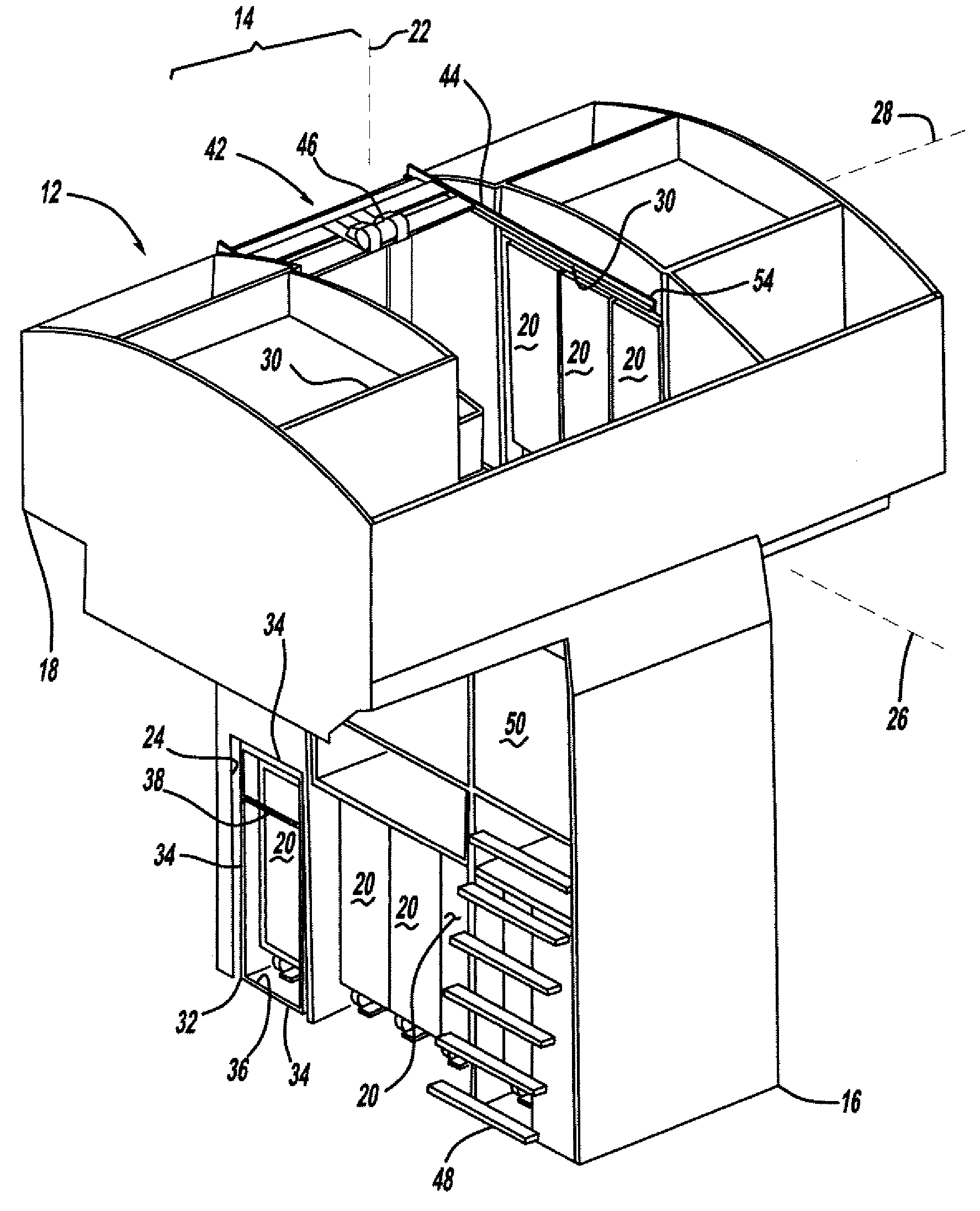
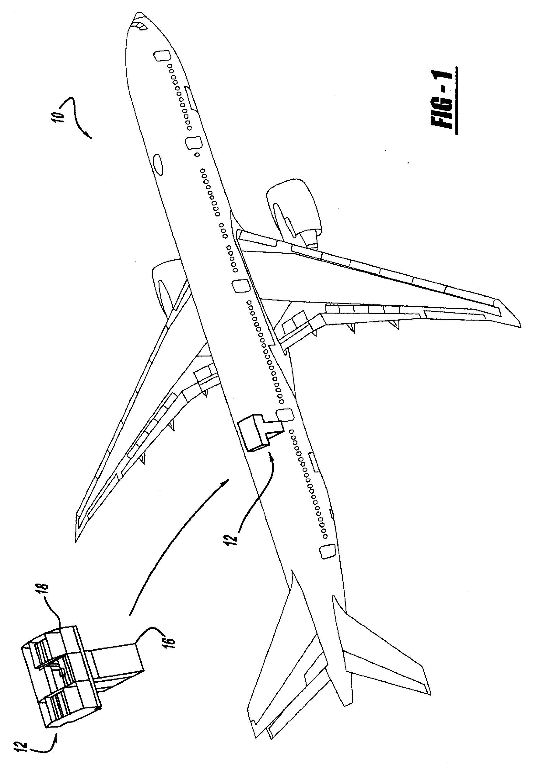
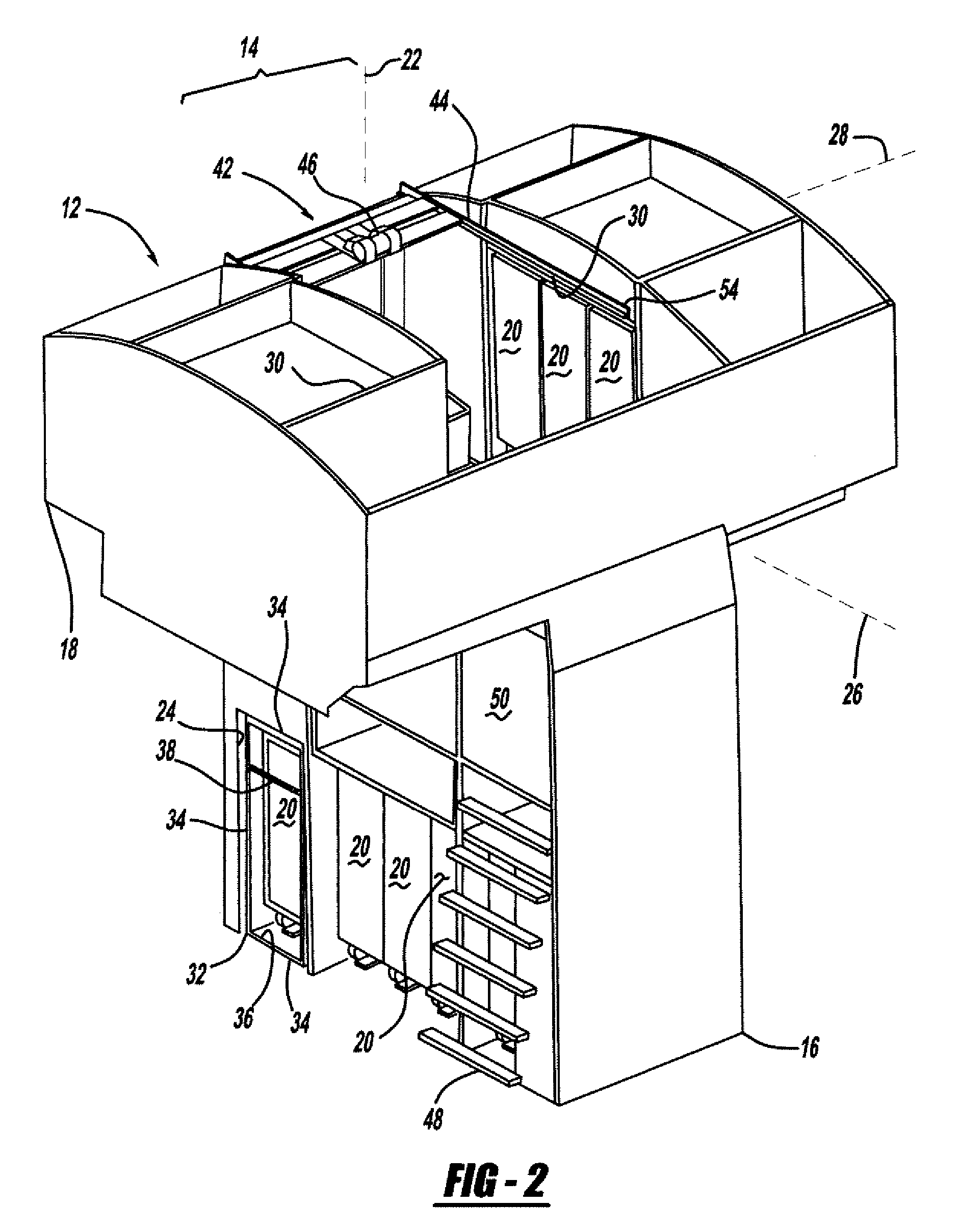
[0038] In the following figures the same reference numerals are utilized for designating the same or similar components in the various views. Moreover, the illustrated embodiments described herein employ features where the context permits, e.g. when a specific result or advantage of the claimed invention is desired. Specifically, the embodiments described herein implement an integrated transport system for moving a galley cart between an overhead sub-module and a main-deck sub-module of a bi-level galley module that is installed in an aircraft. However, it is contemplated that the integrated transport system can be utilized for various other suitable vehicles, buildings, and other environments that require overhead storage. In addition, it will be appreciated that the integrated transport system can be utilized for moving a variety of suitable objects besides galley carts. In this vein, various embodiments are contemplated having different combinations of the described features, hav...


PUM


Abstract

One advantageous embodiment of the present invention is an integrated transport system (14) for moving an object (20) in an aircraft (10) between a main cabin (16) and an overhead cabin (18) via a shaft (24) in connection therebetween. This integrated transport system (14) includes a single-unit gantry-lift device (42) with an object carrier (32) for receiving the object (20). This object carrier (32) has one or more restraint members (34, 38) for securing the object (20) in the object carrier (32) and preventing the object (20) from inadvertently tipping or falling out of the object carrier (32). In this embodiment, the single-unit gantry-lift device (42) further includes a lift device (46) for moving the object carrier (32) generally along a longitudinal axis (22) of the shaft (24) and a gantry device (44) for moving the object carrier (32) generally along a first axis (26) of the overhead cabin (18) and/or a second axis (28), which is disposed generally perpendicular to the first axis (26).

Description

[0001] The present application is a continuation-in-part of U.S. application Ser. No. 10 / 708,955 entitled “AN INTEGRATED TRANSPORT SYSTEM AND METHOD FOR OVERHEAD STOWAGE AND RETRIEVAL,” and filed on Apr. 2, 2004.BACKGROUND OF INVENTION [0002] The present invention relates generally to aircrafts, and more particularly to an integrated transport system and method for moving an object within a bi-level cabin. [0003] Aircraft manufacturers are well known for producing aircrafts having constructions that maximize the use of space within those aircrafts. For example, certain commercial airplanes can have automated elevator systems for vertically moving galley carts between a main deck galley and a lower lobe of the airplane. In this way, the galley carts can be stored in the lower lobe. For that reason, the main-deck passenger cabin can be sized larger than it would otherwise have been if those carts were stored on the main deck. This construction is beneficial because it can allow the ma...

Claims


Application Information

Patent Timeline
Patent Type & Authority Applications(United States)
IPC IPC(8): B64C1/20B64D11/00B64D11/04B64D47/00
CPCB64D11/04B64D11/0007
Inventor HARRINGTON, ANTHONY A.WOJCIECHOWSKI, PAUL M.
Owner THE BOEING CO
Why Eureka
Try Eureka