Gas generating system

a generator and gas technology, applied in the direction of vehicles, pedestrian/occupant safety arrangements, vehicle components, etc., can solve the problem of hazardous inhalation of particulates by vehicle occupants after airbag activation

Inactive Publication Date: 2005-10-20
AUTOMOTIVE SYST LAB
View PDF98 Cites 47 Cited by
  • Summary
  • Abstract
  • Description
  • Claims
  • Application Information

AI Technical Summary

Benefits of technology

[0008] The present invention provides a gas generating system including an igniter, and first and second inflation gas generant compositions positioned to enable fluid communication with the igniter upon activation of the igniter. Flow regulators are provided to regulate a flow of combustion products from the igniter to the first and second inflation gas generant compositions, to correspondingly regulate a time period between activation of the igniter and initiation of combustion of the first and second inflation gas generant compositions. In another aspect, the gas generating system includes a modular baffle system including a first baffle chamber in fluid communication with an inflation gas generant combustion chamber for receiving therein combustion products from combustion of an inflation gas generant positioned in the combustion chamber. An outer baffle chamber is also positioned radially outwardly from the first baffle chamber for receiving therein combustion products from the first baffle chamber. In yet another aspect, the gas generating system includes a first enclosure, a second enclosure, and a projection formed on one of the first enclosure and the second enclosure. An aperture is formed in the other one of the first enclosure and the second enclosure for receiving the projection therein. At least a portion of the projection is fixed within the aperture to prevent withdrawal of the projection from the aperture, thereby securing together the first enclosure and the second enclosure.

Problems solved by technology

Inhalation of the particulates by a vehicle occupant after airbag activation can be hazardous.

Method used


Image

  • Gas generating system
  • Gas generating system
  • Gas generating system

Examples


Embodiment Construction

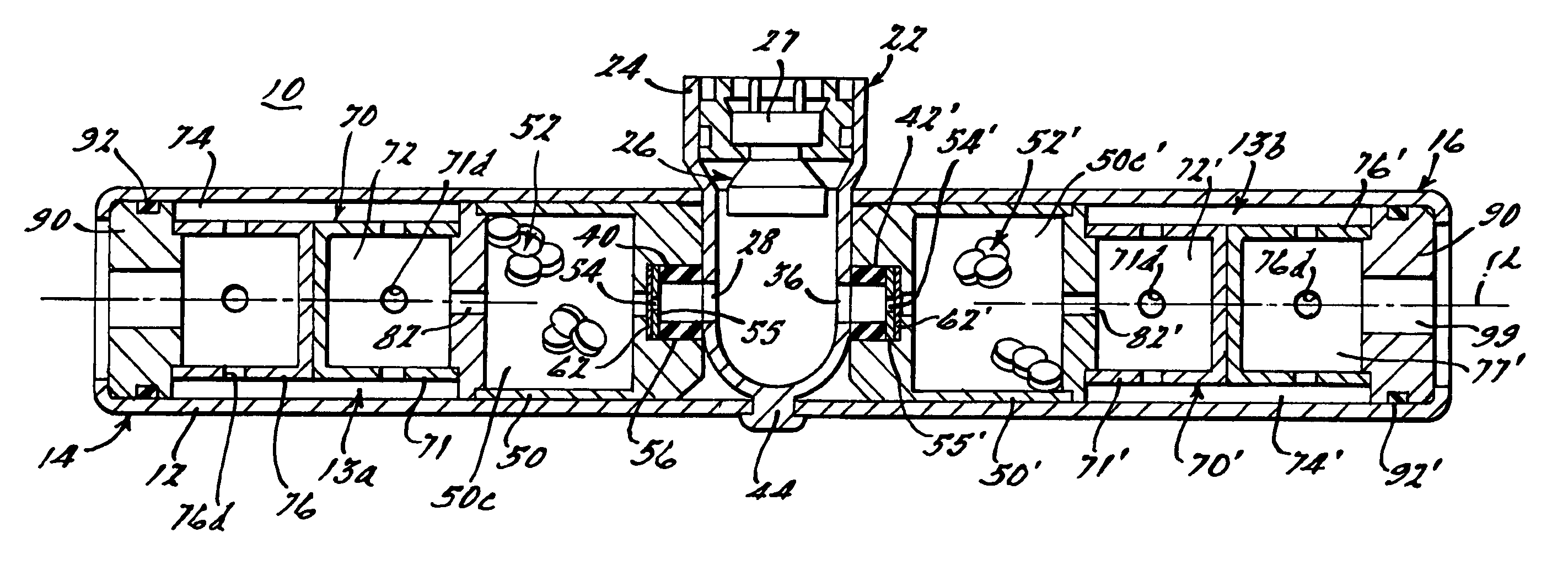
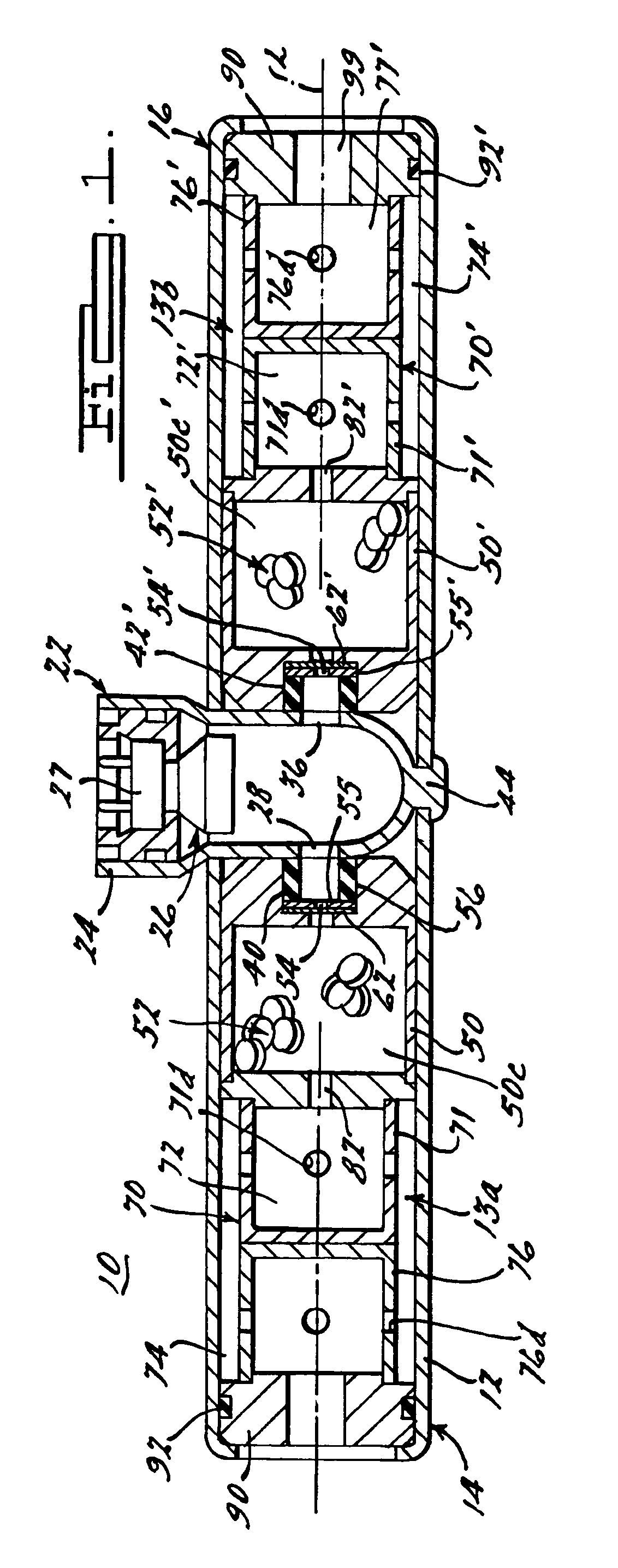
[0019]FIGS. 1-8 show various embodiments of a gas generating system including a gas generator 10 in accordance with the present invention. In the embodiments shown in FIGS. 1-8, gas generator 10 is designed for incorporation into a vehicle occupant protection system 200 (FIG. 8) to generate inflation gas for inflating inflatable elements of the protection system.

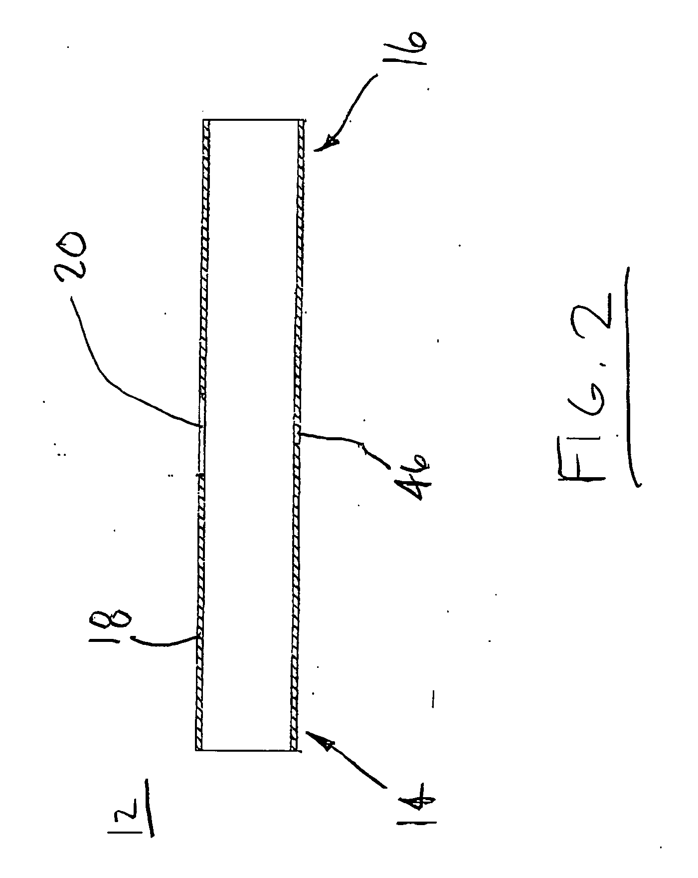
[0020] As seen in FIGS. 1, 2, and 4, gas generator 10 of the present invention includes a substantially cylindrical housing 12 having a first end 14, a second end 16 opposite first end 14, and a wall 18 defining an enclosure for flow of an inflation fluid therethrough upon activation of the gas generating system. A longitudinal axis L extends longitudinally and centrally through housing 12. An opening 20 is formed in wall 18 intermediate first end 14 and second end 16 (and preferably centrally along the length of housing 12) for receiving therein a portion of an igniter assembly 22 (described in greater detail below) used f...


PUM


Abstract

A gas generator (10) includes an igniter (27) and first and second inflation gas generant compositions (52, 52′) positioned to enable fluid communication with the igniter (27) upon activation of the igniter. Flow regulators (54, 54′) are provided to regulate a flow of combustion products from the igniter (27) to the first and second inflation gas generant compositions (52, 52′), to correspondingly regulate a time period between activation of the igniter (27) and initiation of combustion of the first and second inflation gas generant compositions (52, 52′). In another aspect, the gas generator (10) includes a modular baffle system (70) including a first baffle chamber (71) in fluid communication with an inflation gas generant combustion chamber (50) for receiving therein combustion products from combustion of an inflation gas generant (52) positioned in the combustion chamber. An outer baffle chamber (74) is also positioned radially outwardly from the first baffle chamber (71) for receiving therein combustion products from the first baffle chamber. In yet another aspect, the gas generator includes a first enclosure (12), a second enclosure (24), and a projection (44) formed on one of the first enclosure and the second enclosure. An aperture (46) is formed in the other one of the first enclosure (12) and the second enclosure (24) for receiving the projection (44) therein. At least a portion of the projection (44) is fixed within the aperture (46) to prevent withdrawal of the projection (44) from the aperture (46), thereby securing together the first enclosure (12) and the second enclosure (24).

Description

CROSS-REFERENCE TO RELATED APPLICATIONS [0001] This application claims the benefit of U.S. Provisional Application Ser. No. 60 / 563,525, filed on Apr. 19, 2004 and U.S. Provisional Application Ser. No. 60 / 575,687, Filed May 29, 2004.TECHNICAL FIELD [0002] The present invention relates generally to gas generators and, more particularly, to filterless gas generators for use in applications such as inflatable occupant restraint systems in motor vehicles. BACKGROUND OF THE INVENTION [0003] Installation of inflatable occupant restraint systems, generally known as “airbags,” as standard equipment in all new vehicles has intensified the search for smaller, lighter and less expensive restraint systems. Accordingly, since the inflator used in such systems tends to be the heaviest and most expensive component, there is a need for a lighter and less expensive inflator. [0004] A typical inflator includes a cylindrical steel or aluminum housing having a diameter and length related to the vehicle ...

Claims


Application Information

Patent Timeline
Patent Type & Authority Applications(United States)
IPC IPC(8): B60R21/26B60R21/264
CPCB60R21/274B60R21/2644
Inventor BLACKBURN, JEFFERY S.
Owner AUTOMOTIVE SYST LAB
Why Eureka
Try Eureka