Flat panel display device

a display device and flat panel technology, applied in the field of flat panel display devices, can solve the problems of reducing the light coupling efficiency, increasing the weight of the device, and reducing the life span of the battery and the self-luminant devi

Active Publication Date: 2005-10-20
SAMSUNG DISPLAY CO LTD
View PDF7 Cites 54 Cited by
  • Summary
  • Abstract
  • Description
  • Claims
  • Application Information

AI Technical Summary

Benefits of technology

[0012] It is therefore an object of the present inven...

Problems solved by technology

At such an interface, total reflection can occur when the incident angle of light is greater than the critical angle, thus lowering the light coupling efficiency.
For example, if a supplied voltage is rises, the brightness can be improved, however, a ca...

Method used


Image

  • Flat panel display device
  • Flat panel display device
  • Flat panel display device

Examples


first embodiment

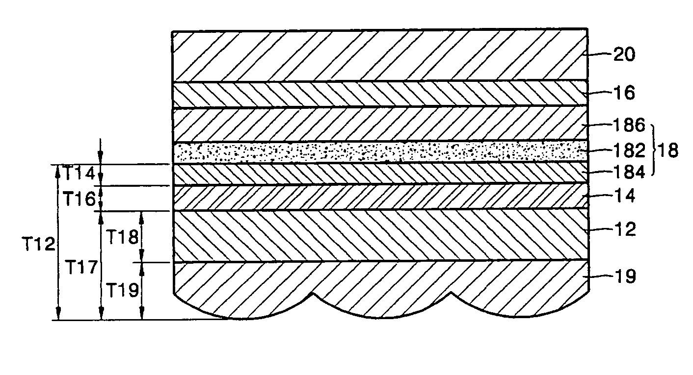
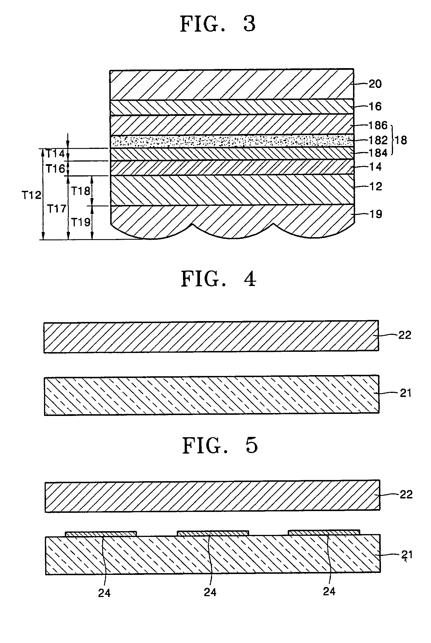
[0042] According to the flat panel display device of the present invention, the self-luminant device is the EL device, and the light emitted from the light emitting layer 182 propagates toward the substrate 12 for the back emission type. However, the emission type is not limited thereto, and the device can be the front emission type or dual emission type, and the self-luminant device does not have to be an EL device.

[0043] In the first embodiment of the present invention, a lens sheet 19 having condensing lenses is formed on the second surface of the substrate 12, and the lens sheet 19 can be made of a glass material having SiO2 or an epoxy based plastic material. In a case where the epoxy based plastic is used as the lens sheet 19, the refractive index thereof is similar to that of glass, which is the material of the substrate 12, and an epoxy based material is also used as an adhesive to attach the lens sheet 19 to the substrate 12, thus reducing the total reflection and improving...

second embodiment

[0054]FIG. 12 is a cross-sectional view illustrating the flat panel display device according to the present invention. In FIG. 12, the flat panel display device is a self-luminant device that is an EL device having a lens sheet and a substrate 32 formed integrally with each other.

[0055] If the transparent electrode is directly formed on the lens sheet and it is used as the substrate of the self-luminant device, the lens sheet and the substrates can be formed integrally with each other, the number of elements is reduced, and the process of manufacturing the device can be simplified. In addition, the distance T22 from the light emitting layer to the exterior portion of the condensing lens in the direction of propagation of the light can be set to be in the range of 50 μm-500 μm in order to prevent the sharpness of the image from being sacrificed. The flat panel display device of front emission type or dual emission type, in which the lens sheet and the sealing substrate are formed int...

third embodiment

[0056]FIG. 13 is a cross-sectional view illustrating a flat panel display device according to the present invention. As illustrated in FIG. 13, the flat panel display device is a self-luminant device of a front emission type organic EL device and the lens sheet 19 is formed between the light emitting layer 182 and a sealing substrate 39.

[0057] The organic EL device has a disadvantage of being prone to degradation by exposure to internal elements such as oxygen from the ITO and reaction between light emitting layer and the interlayer and exterior elements such as humidity, oxygen, ultraviolet rays, and fabricating conditions. Especially, the exterior oxygen and humidity severely affect the life span of the device, thus it is important to package the organic EL device well. Therefore, a protective layer 36 can be formed on the second electrode layer 16 of the organic EL device by depositing various kinds of organic and inorganic materials. Referring to FIG. 13, the lens sheet 19 is lo...


PUM


Abstract

A flat panel display device. The device includes a plurality of self-luminant devices, each of which includes at least a light emitting layer, formed on every pixel, and a lens sheet having a plurality of condensing lenses that correspond to the self-luminant devices and direct the light emitted from the self-luminant devices toward a predetermined direction. A distance between the light emitting layer and an exterior portion of the condensing lens in the direction of propagation of the light is between 50 and 500 microns so as not to overlap images of neighboring sub-pixels, that are expanded by the condensing lenses. Therefore, a lowering of image sharpness that is caused by the condensing lenses can be prevented, while a light coupling efficiency and a brightness are improved.

Description

CLAIM OF PRIORITY [0001] This application makes reference to, incorporates the same herein, and claims all benefits accruing under 35 U.S.C. §119 from an application for FLAT PANEL DISPLAY DEVICE earlier filed in the Korean Intellectual Property Office on 19 Apr. 2004 and there duly assigned Serial No. 2004-26644. BACKGROUND OF THE INVENTION [0002] 1. Field of the Invention [0003] The present invention relates to a flat panel display device, and more particularly, to a flat panel display device having improving a light coupling efficiency from a self-luminant device without sacrificing image sharpness. [0004] 2. Description of the Related Art [0005] In general, a light coupling efficiency of a flat panel display using a self-luminant device is determined by refractive indices of layers from the light emitting layer to the outside of the flat panel display. One portion of the display that lowers the light coupling efficiency is at the interface of a transparent substrate having high ...

Claims


Application Information

Patent Timeline
IPC IPC(8): H01L27/15G02B3/00H01L27/32H01L51/50H05B33/02H05B33/04H05B33/14H05B33/22
CPCH01L27/32H01L2251/558H01L2251/5323H01L51/5275H10K59/00H10K50/858H10K2102/3031H10K2102/351H05B33/22
Inventor SONG, SEUNG-YONGKWON, JANG-HYUKPARK, JIN-WOOCHOI, DONG-SOOLEE, MIN-GYU
Owner SAMSUNG DISPLAY CO LTD
Why Eureka
Try Eureka