Boost controller capable of step-up ratio control

Active Publication Date: 2005-10-20
ROHM CO LTD
View PDF12 Cites 86 Cited by
  • Summary
  • Abstract
  • Description
  • Claims
  • Application Information

AI Technical Summary

Benefits of technology

[0007] The present invention has been done in view of the aforementioned circumstances and its object is to ext

Problems solved by technology

Accordingly, significant

Method used


Image

  • Boost controller capable of step-up ratio control
  • Boost controller capable of step-up ratio control
  • Boost controller capable of step-up ratio control

Examples


Embodiment Construction

[0027] The invention will now be described based on preferred embodiments which do not intend to limit the scope of the present invention but exemplify the invention. All of the features and the combinations thereof described in the embodiment are not necessarily essential to the invention.

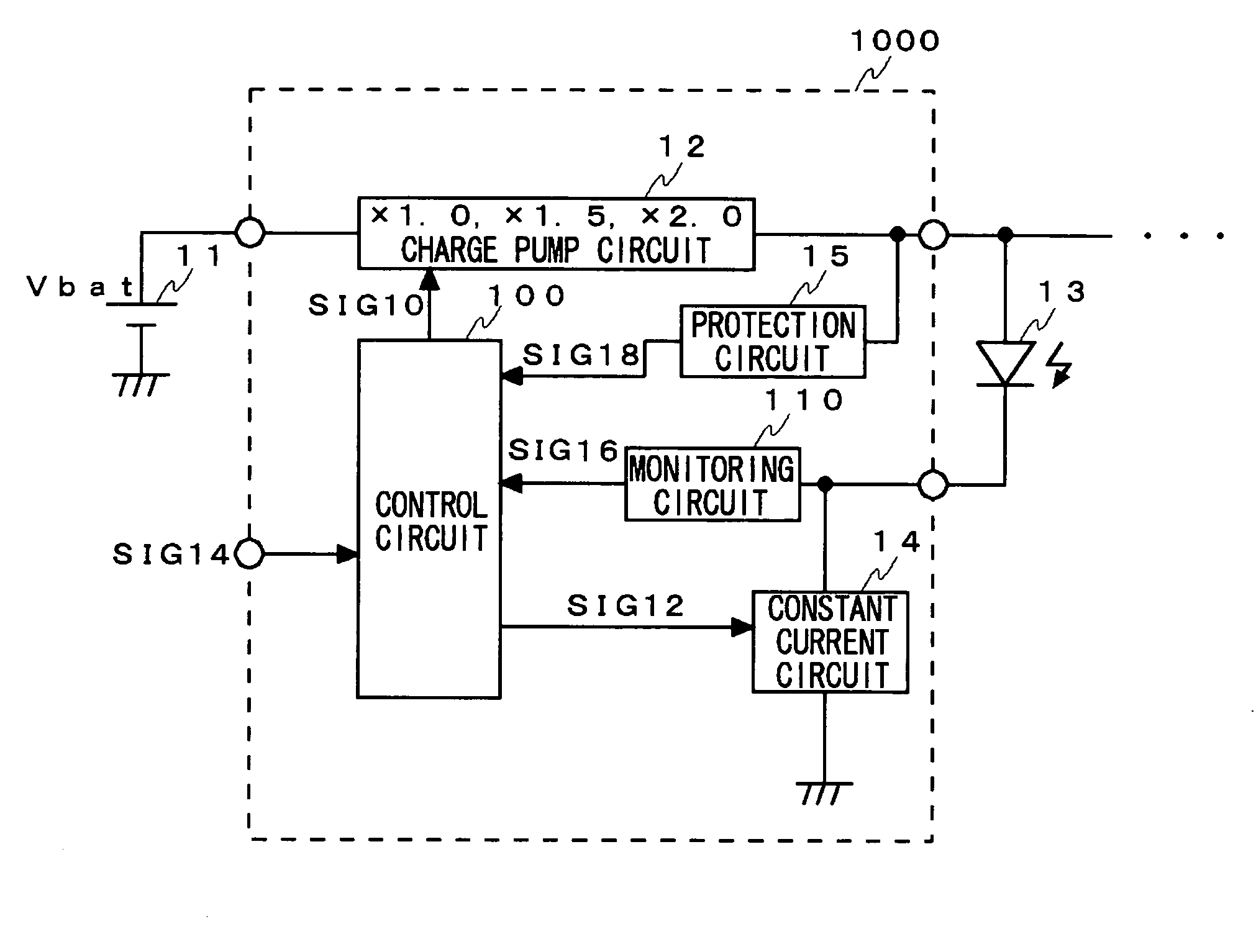
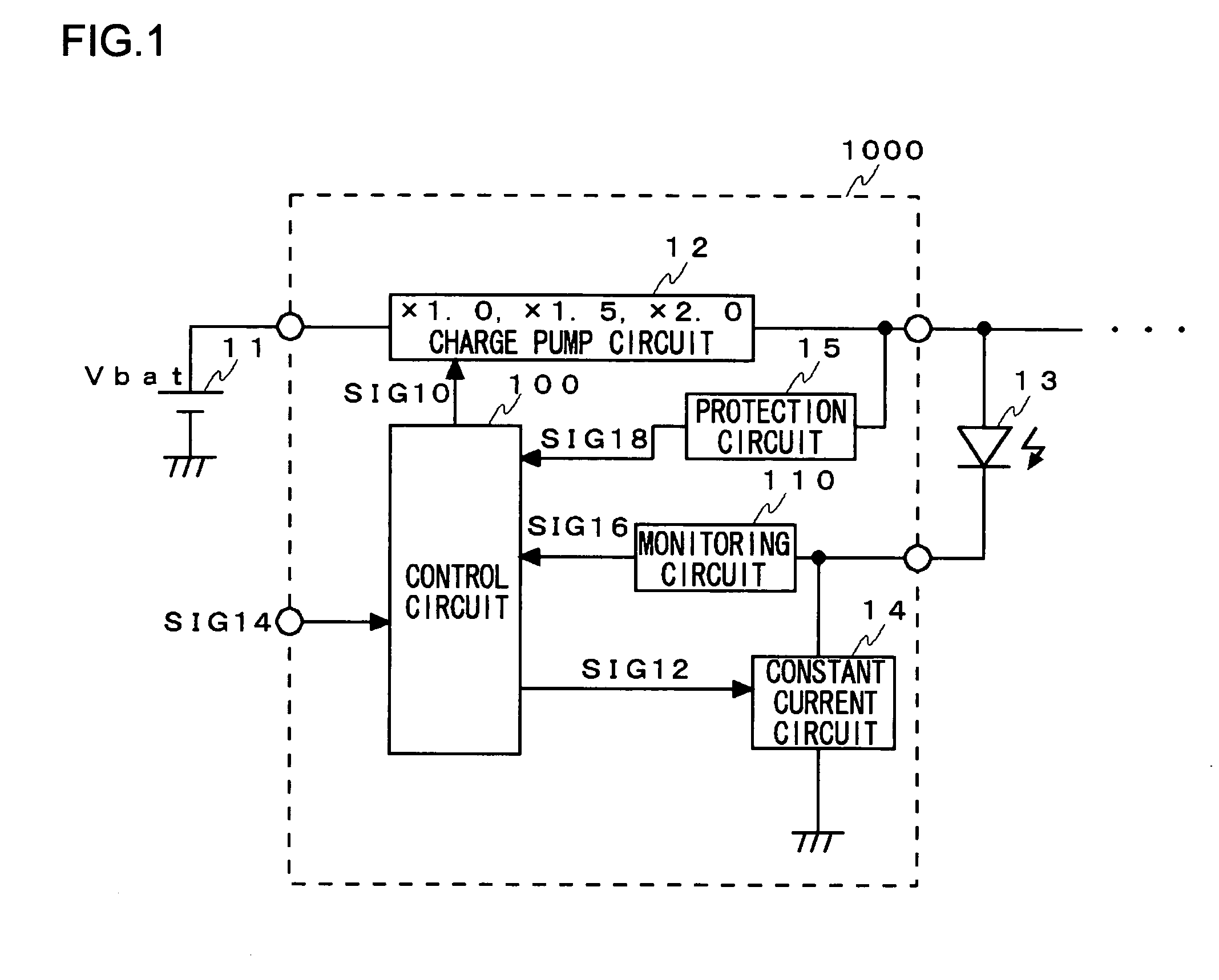
[0028]FIG. 1 is a block diagram illustrating the basic structure of a boost controller according to an embodiment. The boost controller is built in a battery-driven electronic apparatus such as a cell phone and a PDA. The boost controller controls the step-up ratio applied to a battery voltage Vbat of, for example, a lithium-ion battery, which is boosted and then supplied to a load such as an LED 13.

[0029] A boost controller 1000 includes a charge pump circuit 12, a control circuit 100, a monitoring circuit 110, a constant current circuit 14 and a protection circuit 15.

[0030] A battery 11 implemented by a lithium-ion battery generates a battery voltage Vbat of 3.1-4.2V. The charge pump circuit ...


PUM


Abstract

A charge pump circuit boosts a voltage of a battery so as to generate a drive voltage for an LED. A constant current circuit generates a constant current to feed through the LED. A monitoring circuit monitors a cathode potential of the LED, i.e., a voltage across the constant current circuit. A control circuit receives a result of monitoring from the monitoring circuit 110 and increases a step-up ratio of the charge pump circuit when the voltage across the constant current circuit drops below a minimum voltage that guarantees a constant current. The control circuit sets an externally requested constant current value in the constant current circuit. When a change from a large current to a small current is requested, the control circuit returns the step-up ratio of the charge pump circuit to 1.0.

Description

BACKGROUND OF THE INVENTION [0001] 1. Field of the Invention [0002] The present invention relates to a boost controller that controls a boost circuit for boosting a battery power supply and supplying the boosted power to a load, and to an electronic apparatus that includes the boost controller. [0003] 2. Description of the Related Art [0004] Light-emitting diodes (LED) of various types are used in battery-driven portable equipment such as cell phones and personal data assistants (PDA). For example, an LED is used as backlight for a liquid crystal display (LCD). Lithium-ion batteries are commonly used in battery-driven portable equipment. A lithium-ion battery generates a battery voltage of about 3.1-4.2V. A white LED requires a driving voltage of about 3.3-4.0V. Therefore, a charge pump circuit is required to boost the battery voltage. Patent document No. 1 discloses a method of controlling a charge-pump regulated dc-dc converter. [Patent document No. 1][0005] Japanese Published Pa...

Claims


Application Information

Patent Timeline
IPC IPC(8): G05F1/56H02J7/00H02M3/00H02M3/07H05B37/02H05B45/59
CPCH05B33/0884H05B33/0815H05B45/38H05B45/59H10K59/1315H10K59/1795H10K50/824
Inventor YAMAMOTO, ISAOARAKI, KYOICHIROKAGEMOTO, NOBORU
Owner ROHM CO LTD
Why Eureka
Try Eureka