Driving device and an optical apparatus

Inactive Publication Date: 2005-10-20
KONICA MINOLTA OPTO
View PDF3 Cites 25 Cited by
  • Summary
  • Abstract
  • Description
  • Claims
  • Application Information

AI Technical Summary

Benefits of technology

[0011] It is another object of the present invention to provide a driving device which can precisely detect the position of a movable member by an inexpensive and simple construction, and an optical apparatus using this driving device.

Problems solved by technology

This is disadvantageous in terms of costs and reliability due to the complicated detecting circuit.
Another problem is that it is difficult to precisely produce the field magnet in which the N-pole and the S-pole are alternately arranged to have a high resolution.
(1) The driving device of the second publication adopts a contacting sensing method for detecting the position of the movable member using the electrical resistance of the driving member, and it is difficult to obtain a high resolution since the contact resistance of the movable member and the driving member varies.
It is difficult to select the material for the driving member capable of providing a sufficient electrical resistance value for the sensing and the high rigidity.
(2) Although the driving device of the third publication adopts the non-contacting sensing means different from the above, an ac voltage needs to be applied to either the movable electrode or the fixed electrode, which is disadvantageous in terms of costs and reliability due to the complicated detecting circuit.
Another problem is that the clearance between the fixed electrode and the movable electrode has to be minimized in order to obtain a high resolution.
Another problem from another angle is a reduction in the precision in detecting the position of the movable member resulting from a change in the operating environment of the driving device.

Method used


Image

  • Driving device and an optical apparatus
  • Driving device and an optical apparatus
  • Driving device and an optical apparatus

Examples


Embodiment Construction

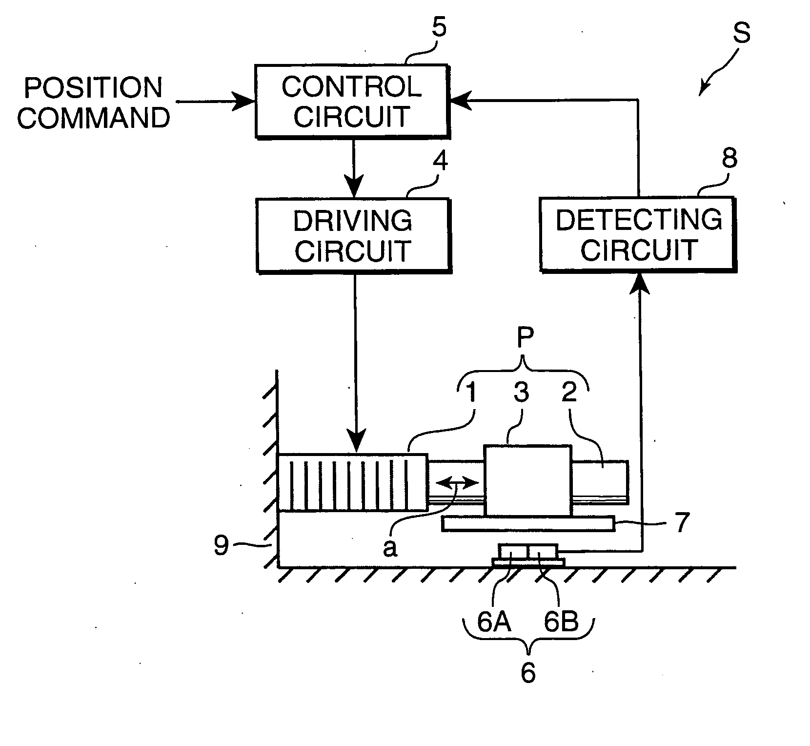
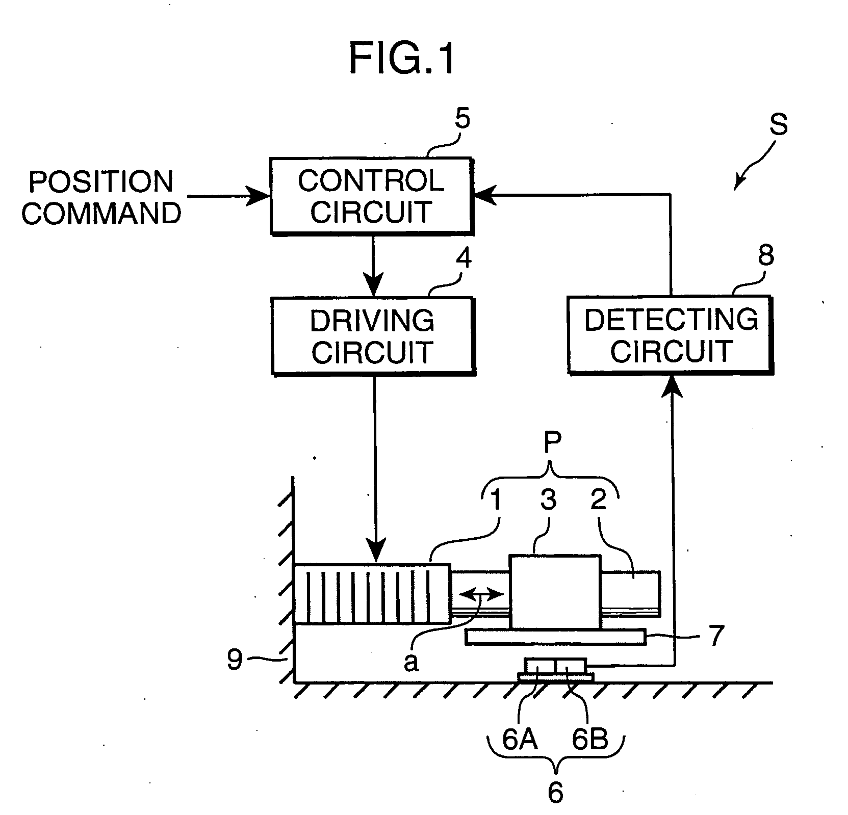
[0025] Referring to FIG. 1 showing a system construction of a driving device S according to an embodiment of the present invention, the driving device S is provided with a piezoelectric actuator or driver P, a driving circuit 4 for driving the piezoelectric actuator P, a control circuit 5, a magnetic field generating member 7 which is integrally attached to a movable member 3 of the piezoelectric actuator P and whose surface magnetic flux density changes along advancing and retreating directions, a magnetic field detector 6 for detecting a magnetic field generated by the magnetic field generating member 7, and a detecting circuit or calculator 8 for detecting the position of the movable member 3 in accordance with a detection signal of the magnetic field detector 6. It should be noted that the magnetic field detector 6, the magnetic field generating member 7 and the detecting circuit 8 construct a position sensing section for the movable member 3.

[0026] The piezoelectric actuator P...


PUM


Abstract

A driving device is provided with a piezoelectric actuator, a magnetic field generating member integrally attached to a movable member of the piezoelectric actuator and having a surface magnetic flux density that changes along advancing and retreating directions of the movable member, a magnetic field detector for detecting a magnetic field generated by the magnetic field generating member, and a detecting circuit for calculating the position of the movable member in accordance with a detection signal of the magnetic field detector. The magnetic field detector includes first and second magnetic field detecting elements fixedly juxtaposed near a movement path of the magnetic field generating member. The driving device is capable of precisely detecting the position of the movable member by an inexpensive and simpler construction, and is applicable for an optical apparatus.

Description

[0001] This application is based on patent application No. 2004-101091 filed in Japan, the contents of which are hereby incorporated by references. BACKGROUND OF THE INVENTION [0002] The present invention relates to a driving device applied to various precision driving units and particularly to a driving device suitably applied to a lens driving mechanism or the like of an optical apparatus such as an electronic camera, an image sensing apparatus or a light pickup. [0003] Various driving devices have been proposed as those to be applied to lens driving mechanisms of image sensing apparatuses, light pickups and the like. The driving devices can be roughly divided into those of the magnetic source type using an electromagnetic motor as a driving source and those of the nonmagnetic source type using a piezoelectric actuator or the like as a driving source. As one example of the former type, a driving device in which a driving field magnet is stationarily fixed relative to a movable mem...

Claims


Application Information

Patent Timeline
IPC IPC(8): G01D5/14G02B7/08G02B7/04G11B7/00G11B7/125G11B7/135H01L41/09
CPCG01D5/145H02N2/025G02B7/08
Inventor HOSHINO, TAKAYUKI
Owner KONICA MINOLTA OPTO
Why Eureka
Try Eureka