Bearing unit for wheels

a technology for bearing units and wheels, applied in mechanical actuated clutches, braking discs, transportation and packaging, etc., can solve the problems of difficult to obtain a perfect right angle, judder and small runout of the side surface of the rotor in the direction of the rotation axis, so as to prevent deformation of the installation surface, inhibit the runout of the friction surface, and inhibit the effect of judder during braking

Inactive Publication Date: 2005-10-20
NSK LTD
View PDF9 Cites 4 Cited by
  • Summary
  • Abstract
  • Description
  • Claims
  • Application Information

AI Technical Summary

Benefits of technology

[0024] With the bearing unit for wheel of the present invention configured as described above, it is possible to inhibit judder during braking. In other words, even when the opening edge peripheral portions of the installation holes protrude in a direction such that they are convex with respect to the installation surface due to the engagement between the outer peripheral surface of the studs and the inner peripheral surface of the installation holes during the press insertion of the studs, the protrusion occurs only inside the concave groove located in the opening edge peripheral portion. Therefore, it is possible to prevent deformation of the installation surface due to this protrusion, and thus it becomes difficult for the friction surface for braking of the rotating member for braking that is fixed to the installation surface to run out. Also, even when the amount of protrusion of each installation holes differs, such protrusions occur inside the concave groove as described above, so that it is possible to inhibit the runout of the friction surface for braking of the rotating member for braking due to the difference in protruding amounts. As a result, it is possible to inhibit the judder due to this kind of runout of the friction surface for braking.
[0025] Furthermore, when the width in the radial direction of the concave groove is taken to be W and the inner diameter of the installation holes is taken to be d, then W=d+(5 to 25 mm). In other words, the minimum distance from the opening edges of the installation holes to the edge in the width direction of the concave groove is 2.5 to 12.5 mm. Therefore, while inhibiting the deformation of the installation surface due to the protrusion described above, it is possible to maintain the area of contact between the installation surface and the rotating member for braking, and to stably support (without any runout) the rotating member for braking. When the width W of the concave groove is less than d+5 mm (D<d+5 mm) (the distance from the opening edges of the installation holes to the edge in the width direction of the concave groove becomes less than 2.5 mm), it becomes easy for the installation surface to deform due to the press fitting of the studs. Also, when the installation surface deforms, the runout of the friction surface for braking of the rotating member for braking becomes large, and it becomes easy for judder to occur. On the other hand, when the width W of the concave groove is greater than d+25 mm (D>d+25 mm) (the distance from the opening edges of the installation holes to the edge in the width direction of the concave groove becomes greater than 12.5 mm), it becomes difficult to maintain the contact area between the installation surface and the rotating member for braking. Particularly, when the nuts are screwed onto the studs and tightened, the deformation of the rotating member for braking becomes large, so that the support of the rotating member for braking becomes unstable (it becomes easy for runout to occur). As a result, the runout of the friction surface for braking of the rotating member for braking becomes large and it become easy for judder to occur.

Problems solved by technology

Meanwhile, it is known that a vibration with unpleasant noise called judder often occurs during braking of an automobile.
Namely, while the surface of the rotor 2 has to be originally assembled to be at right angle with the center of rotation of the rotor 2, due to unavoidable tolerances during manufacturing, it is difficult to obtain a perfect right angle.
As a result, when driving an automobile, a little runout of the side surface of the rotor 2 in the direction of the rotation axis (in the right and left direction in FIG. 1) cannot be avoided.
However, in the case of a conventional bearing unit for wheel, there was a possibility that this kind of runout of the friction surface for braking of the rotating member for braking (side surfaces of a rotor 2, or an inner peripheral surface of a drum) would occur easily due to the following reasons.
As a result, there is a possibility that the friction surface for braking of the rotating member for braking, which is fixed onto the installation surface 14, becomes prone to run out.
Particularly, when the amount that the opening edge peripheral portion protrude differ for each installation hole 15, it becomes easy for the friction surface for braking of the rotating member for braking that is connected to and fixed on the installation surface 14 to run out, so this condition is undesirable.

Method used


Image

  • Bearing unit for wheels
  • Bearing unit for wheels
  • Bearing unit for wheels

Examples


Embodiment Construction

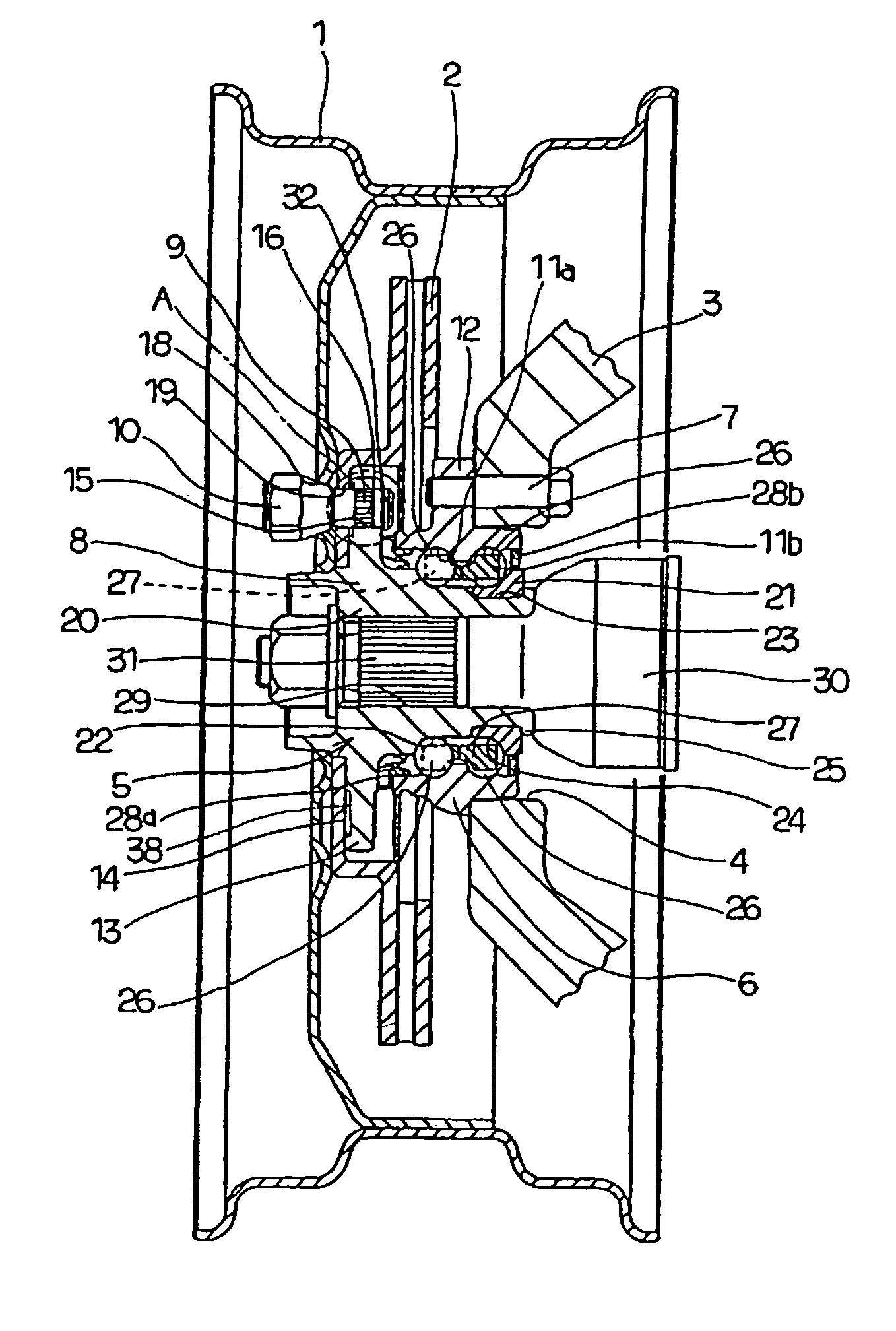
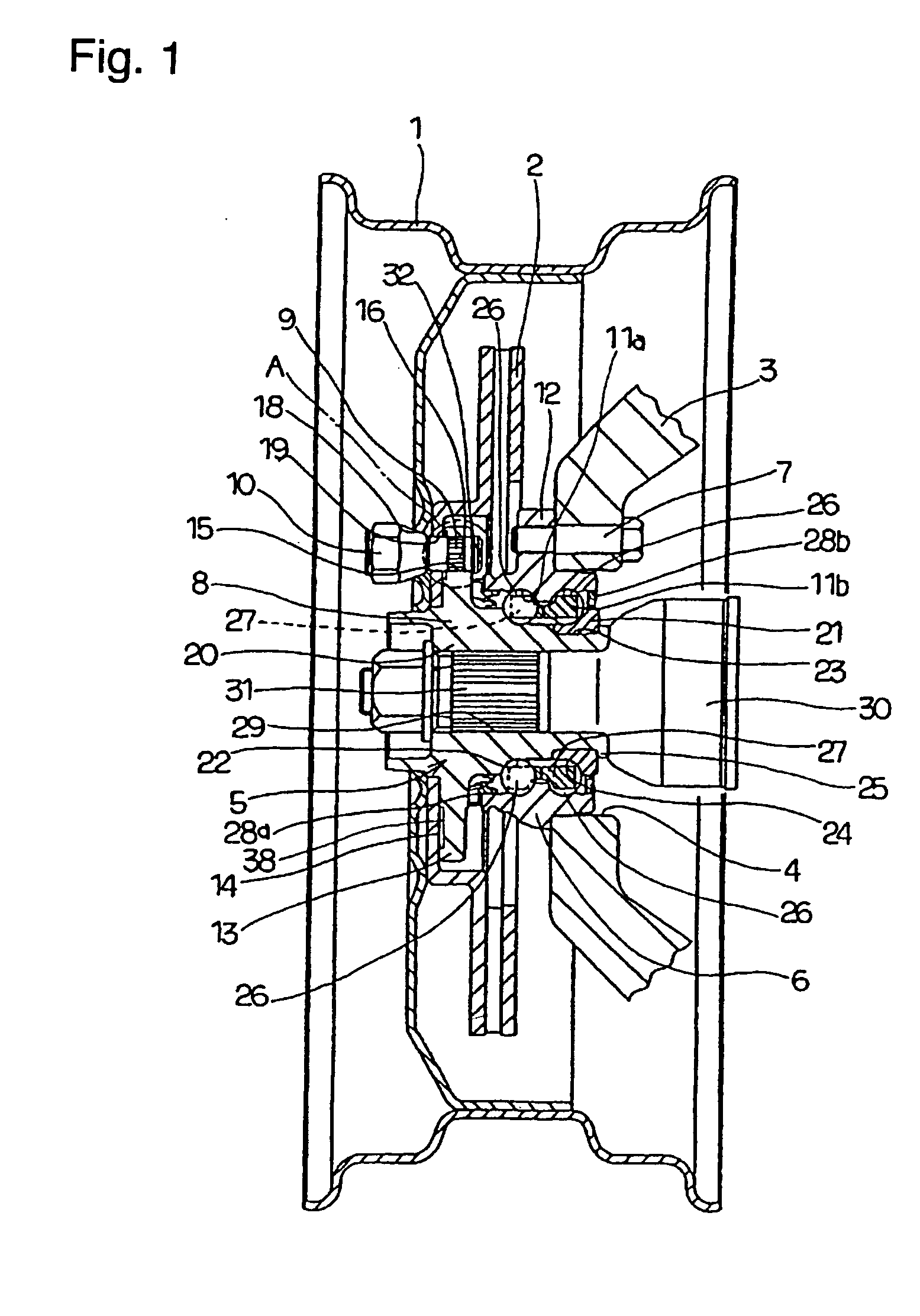
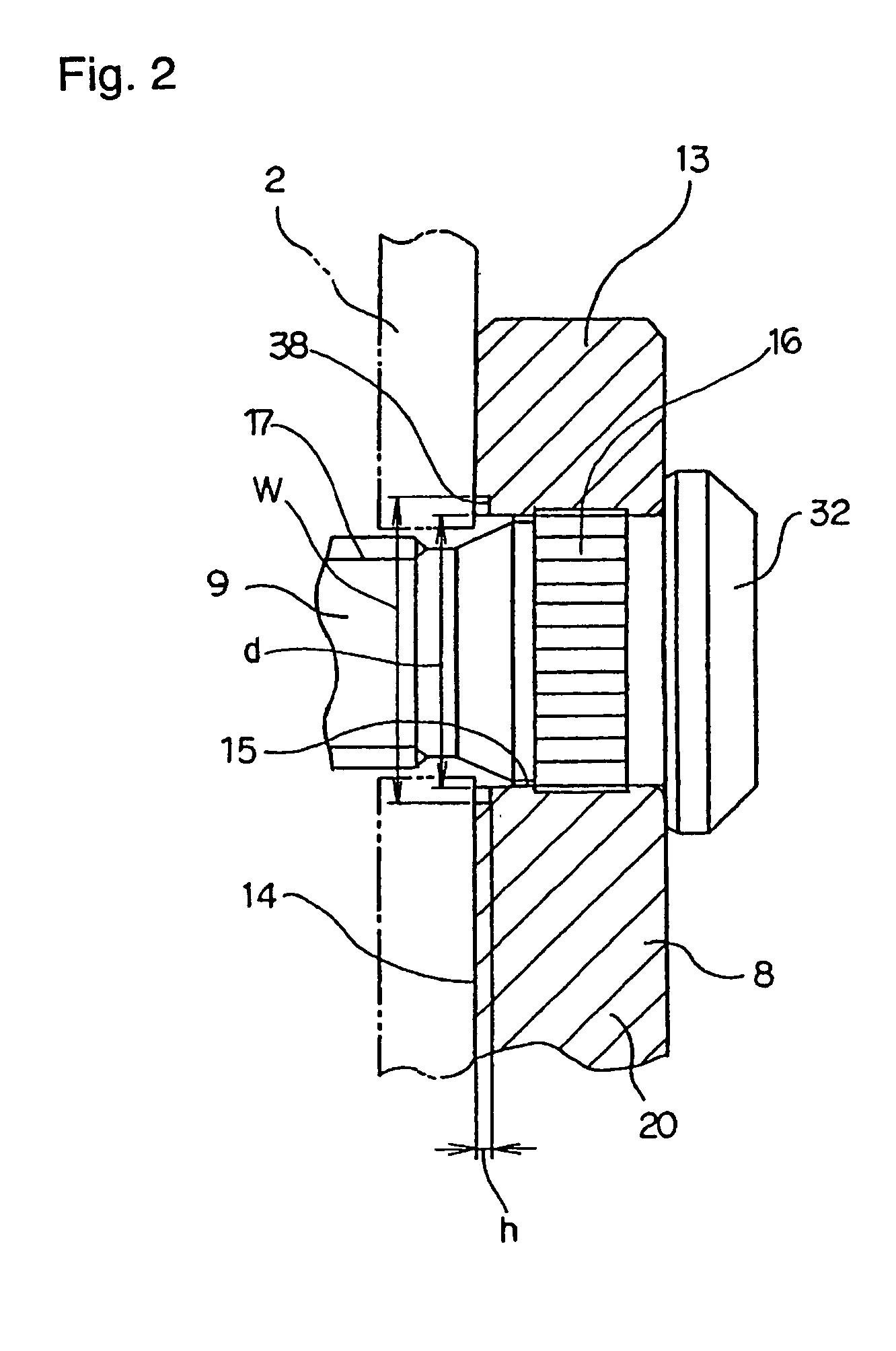
[0033] FIGS. 1 to 3 show a first example of the embodiment of the present invention. The feature of the present invention is sufficiently securing the surface precision of the installation surface 14, which is one side surface of the installation flange 13 that is formed on the outer peripheral surface of the hub 8 as a rotating member, so as to inhibit the runout of the rotor 2, which is a rotating member for braking. The other basic structures and functions of bearing unit for wheel 5 are the same as those explained above for the prior art with reference to FIG. 1, so any redundant explanation will be omitted or simplified, and the following description is focused on the feature of the present invention.

[0034] The outer peripheral surface of the hub body 20 of the hub 8 is provided with the installation flange 13 for fixing the wheel 1 of a traveling wheel and the rotor 2 as a rotating member for braking. The installation holes 15 are formed at a plurality of positions (5 in the ...


PUM


Abstract

A concave groove 38 is formed all the way around the circumference on a part of an installation surface 14 having its center at the central axis of a hub 8, such that it is concave inward from the installation surface. Also, installation holes 15 for press fitting studs 9 thereto are opened on a substantially middle section in the width direction of a bottom section of the concave groove 38. When W is taken to be the width of the concave groove in the radial direction and d is taken to be the inner diameter of the installation holes, then W=d+(5 to 25 mm). By this configuration, it is possible to inhibit the deformation of the installation surface 14 by the press insertion of the studs 9, so the above problems can be solved. Thereby, judder is prevented from occurring during braking by inhibiting runout of the rotor 2 fixed to the installation surface 14 of the installation flange 13.

Description

BACKGROUND OF THE INVENTION [0001] 1. Field of the Invention [0002] This invention relates to an improvement of a bearing unit for wheel for supporting a wheel for automobile and rotating members for braking such as a rotor, a brake drum and so forth. [0003] 2. Description of Background Art [0004] A wheel 1 constituting a wheel of an automobile and a rotor 2 of a disk brake functioning as a damping device are rotatably supported by a knuckle 3 of a suspension device, for example, in the structure as illustrated in FIG. 1 showing a first example of the embodiment of the present invention. That is, an outer ring 6 of a bearing unit 5 for wheel, which is a stationary member that does not rotate even in use, is fixed to circular support holes 4 that are formed in the knuckle 3 by a plurality of bolts 7. On the other hand, the wheel 1 and rotor 2 are securely connected to a hub 8 of the bearing unit 5, which is a rotating member that rotates in use, by a plurality of studs 9 and nuts 10....

Claims


Application Information

Patent Timeline
Patent Type & Authority Applications(United States)
IPC IPC(8): B60B27/00F16D65/12
CPCB60B27/00F16D2065/1384F16D2065/1376F16D65/123
Inventor SAKAMOTO, JUNSHI
Owner NSK LTD
Why Eureka
Try Eureka