Apparatus and method of measuring the flying behavior of a flying body

a flying body and flying behavior technology, applied in the field of apparatus and a flying body flying behavior measurement method, can solve the problems of inability to photograph the entire mark, inability to change the setting of the measurement apparatus, so as to achieve the effect of high precision, easy measurement, and reduced measurement accuracy

Inactive Publication Date: 2005-10-20
NAT UNIV CORP YOKOHAMA NAT UNIV +1
View PDF1 Cites 33 Cited by
  • Summary
  • Abstract
  • Description
  • Claims
  • Application Information

AI Technical Summary

Benefits of technology

[0020] In order to solve problems based on the conventional techniques described above, an object of the present invention is to provide an apparatus and a method of measuring the flying behavior of a flying body, capable of measuring the flying behavior of a spherical flying body, such as a golf ball with ease and high precision.
[0032] The measuring apparatus according to the present invention includes: a recording portion that records a spherical flying body in a first image of the flying body and a second image of the flying body recorded at different points in time; image information computing portion that detects a first outline region of the flying body in the first image of the flying body, finds first image information from the first image of the flying body in at least a portion of the first outline region, detects a second outline region of the flying body in the second image of the flying body, and finds second image information from the second image of the flying body in the second outline region; and rotation amount computing portion that maps the first image information to a surface of a first virtual spherical body, maps the second image information to a surface of a second virtual spherical body, and computes a rotation amount that is used for rotation processing when the rotation processing is performed on the first virtual spherical body to obtain a highest correlation between the first image information on the surface of the first virtual spherical body and the second image information of the second virtual spherical body. The rotation amount of the flying body can thus be computed by using the first image information and the second image information, without providing a specialized mark or the like on a surface of the flying body. Accordingly, the flying behavior of the flying body can be measured with ease and high precision, without any decreases in the measurement precision due to undetectability of a portion of the mark.
[0033] The method of measuring a flying behavior of a flying body according to the present invention includes: optically recording a spherical flying body during flight at points in time with a predetermined interval of time therebetween; detecting a first outline region of the flying body in a first image of the flying body; finding first image information from the first image of the flying body in at least a portion of the first outline region; detecting a second outline region of the flying body in the second image of the flying body; finding second image information from the second image of the flying body in the second outline region; mapping the first image information to a surface of a first three-dimensional virtual spherical body; mapping the second image information to a surface of a second three-dimensional spherical body; performing rotation processing on the first virtual spherical body; and computing a rotation amount that is used for the rotation processing when a highest correlation is obtained between the first image information on the surface of the first virtual spherical body and the second image information on the surface of the second virtual spherical body. The rotation amount of the flying body can thus be computed from the recorded image of the spherical flying body by using the first image information and the second image information, without providing a specialized mark or the like on a surface of the flying body. Accordingly, the flying behavior of the flying body can be measured with ease and high precision, without any decreases in the measurement precision due to undetectability of a portion of the mark.

Problems solved by technology

However, a portion of the mark will be hidden, and the entire mark will thus be unable to be photographed, if the golf ball rotates about a rotation axis that is parallel to the photographed surface of the golf ball.
The marks being tracked may be hidden in part, and thus there is a fear that the precision in measuring the rotation amount of the golf ball will decrease.
Then, another problem will exist in that changes to settings on the measurement apparatus are unavoidable because measurement conditions are changed.
Measurement work thus becomes complex.

Method used


Image

  • Apparatus and method of measuring the flying behavior of a flying body
  • Apparatus and method of measuring the flying behavior of a flying body
  • Apparatus and method of measuring the flying behavior of a flying body

Examples


second embodiment

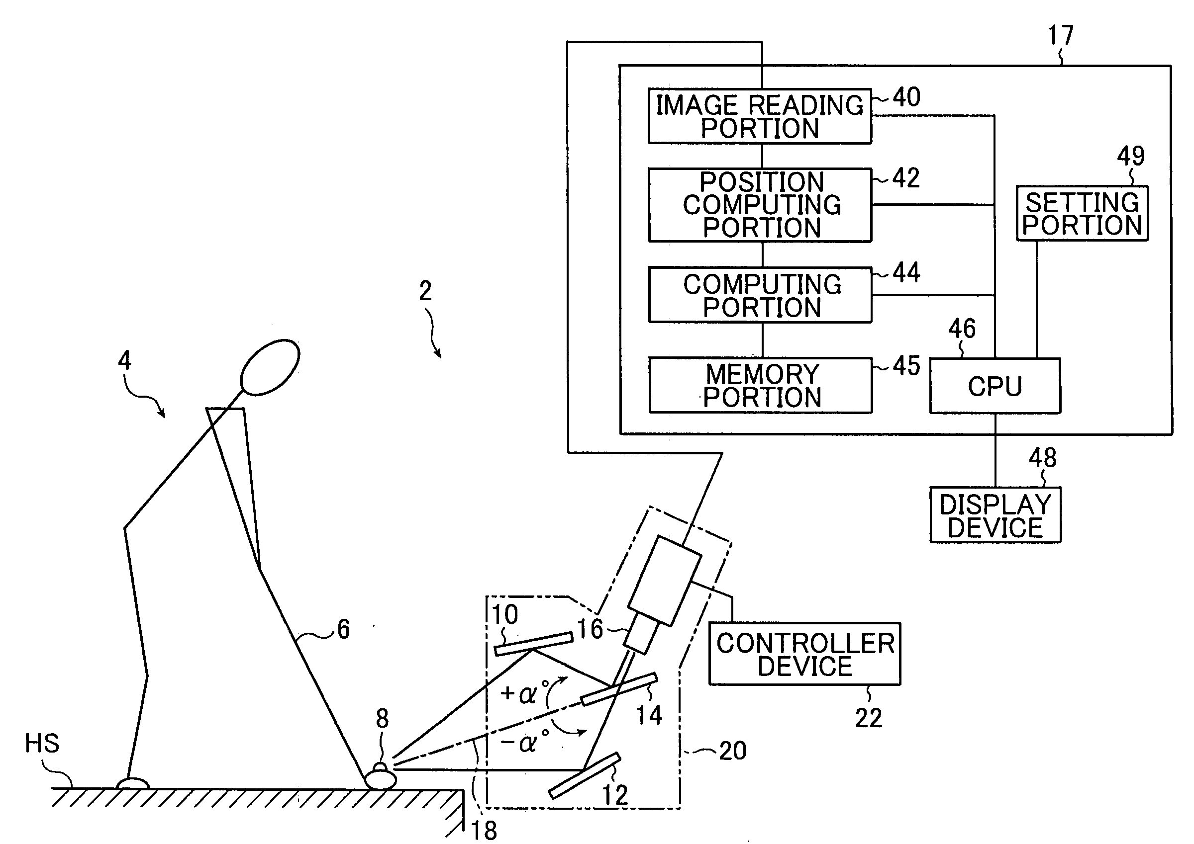
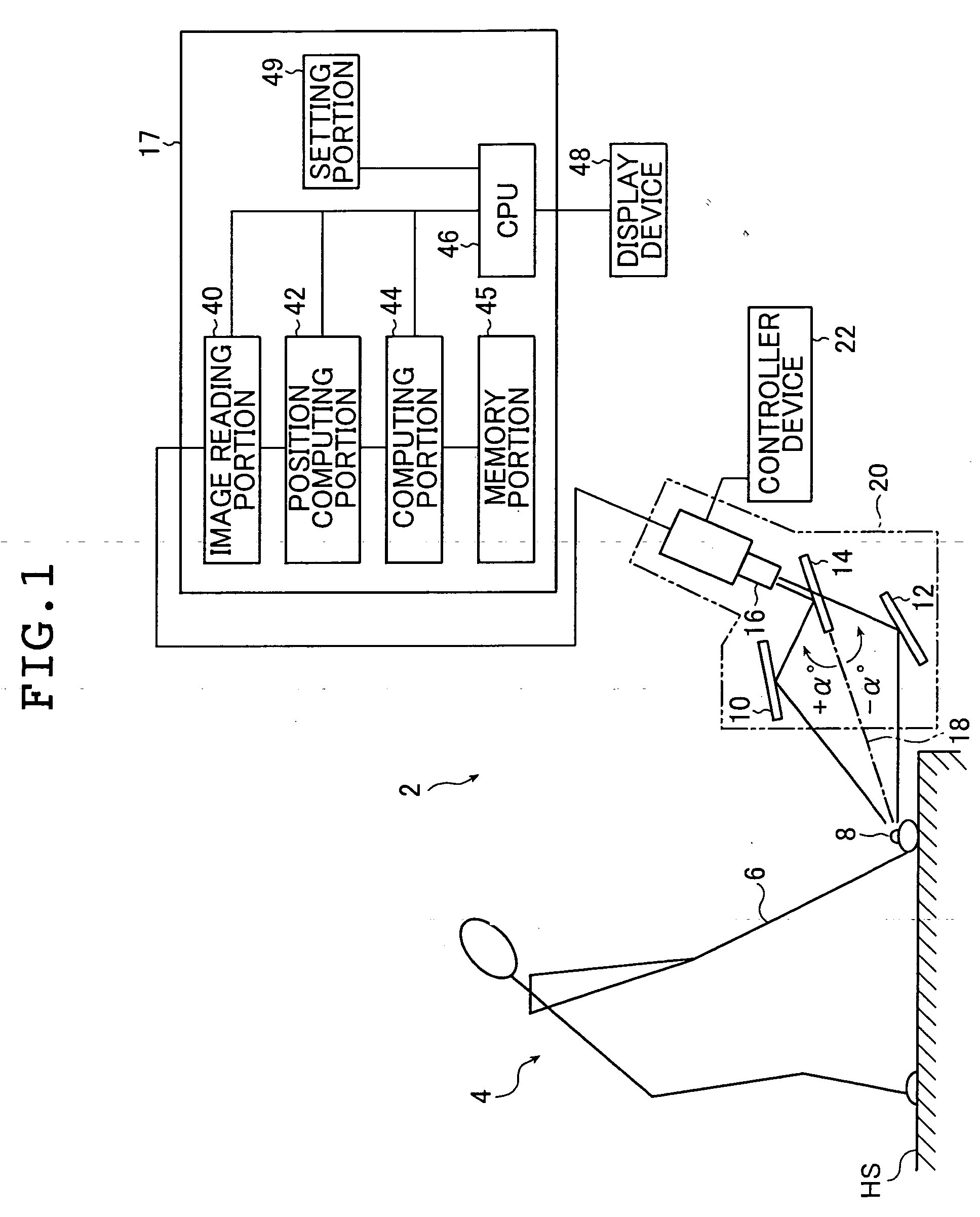
[0151] a measuring apparatus of the present invention is explained next.

[0152]FIG. 10 is a planar view that schematically shows the second embodiment of the present invention. It should be noted that symbols identical to those used in the first embodiment are provided to constituent elements that are similar to those of the initial trajectory measuring apparatus 2 of the first embodiment shown in FIG. 1. Detailed explanations of such constituent elements are omitted.

first embodiment

[0153] An initial trajectory measuring apparatus 2a for a golf ball of this embodiment shown in FIG. 10 has a different mirror arrangement compared to that of the initial trajectory measuring apparatus 2 shown in FIG. 1. The other configurations are similar to those of the initial trajectory measuring apparatus of the first embodiment, and detailed explanations thereof are omitted here.

[0154] Referring to FIG. 10, The initial trajectory measuring apparatus 2a has mirrors 80 and 82, an adjustment mirror 84, a half mirror 86, a CCD camera 90, a controller device 22a connected to the CCD camera 90, and an initial trajectory parameter computation portion 17.

[0155] The mirrors 80 and 82, the adjustment mirror 84, the half mirror 86, and the CCD camera 90 configure a main body portion 92. It is possible to make the main body portion 92 portable by housing it in a case 20a. The controller device 22a is connected to the CCD camera 90. The controller device 22a is also connected to the init...

third embodiment

[0176]FIGS. 11A and 11B are schematic diagrams that show a process order of a method of measurement employed by an initial trajectory measuring apparatus, which is an example of a measuring apparatus according to the present invention.

[0177] In FIG. 11A the golf ball image 60 is recorded initially, and a golf ball image 62 is recorded after a predetermined period of time has elapsed. In this case a portion of the logo 61 is hidden after the predetermined period of time has elapsed, resulting in a logo 63. Automated measurements cannot be performed by a conventional method when a portion of the logo 63 is thus hidden.

[0178] The golf ball image 60 undergoes binarization processing, for example, in this embodiment. A density pattern of the logo 61 portion is thus obtained. The density pattern is expressed by a mark 61a mapped onto the surface of the first virtual sphere Q shown in FIG. 11B. The mark 61a is set as a specific point (density pattern). The golf ball image obtained after t...


PUM


Abstract

A measuring apparatus of a flying behavior of a spherical flying body has: a recording portion that optically records the flying body during flight with a predetermined interval of time, to obtain a first image and a second image of the fling body; image information computing portion that detects a first outline region of the flying body in the first image of the flying body and a second outline region of the flying body from the second image of the flying body, and finds first image information from the first image of the flying body in at least a portion of the first outline region and second image information from the second image of the flying body in the second outline region; and rotation amount computing portion that maps the first image information to a surface of a first virtual spherical body, the second image information to a surface of a second virtual spherical body, and computes a rotation amount that is used for rotation processing when the rotation processing is performed on the first virtual spherical body to obtain a highest correlation between the first image information and the second image information.

Description

INCORPORATION BY REFERENCE [0001] This application claims priority on Japanese patent application No. 2004-105165, the entire contents of which are hereby incorporated by reference. BACKGROUND OF THE INVENTION [0002] The present invention relates to an apparatus and a method of measuring a flying behavior of a flying body, the apparatus and method being capable of measuring the flying behavior of the spherical flying body such as a golf ball with ease and high precision. [0003] Measurement of the flying behavior of flying bodies is currently performed. For example, the flying behavior of a golf ball immediately after impact is measured by using images, based on which image measurements are made for simulating the carry distance of the golf ball. [0004] A variety of flying behaviors of a golf ball may be found by using image measurement, such as velocity and movement direction. The velocity and angles of movement of a golf ball can be found by recording images at points in time with ...

Claims


Application Information

Patent Timeline
Patent Type & Authority Applications(United States)
IPC IPC(8): A63B69/36A63B53/04G01P3/36G01P3/68G01P3/80G06T7/00G06T7/20
CPCA63B69/3658A63B2220/35A63B2102/32G06T2207/30221G06T2207/30241G06T7/246G06T7/73G06T7/20
Inventor NISHINO, KOICHISAEGUSA, HIROSHI
Owner NAT UNIV CORP YOKOHAMA NAT UNIV
Why Eureka
Try Eureka