Proection pad for the trochantheric region and device comprising the pad

a technology for trochantheric region and proection pad, which is applied in the direction of protective garments, medical science, garments, etc., can solve the problems of significant damage to the surrounding soft tissue, and achieve the effects of improving heat and moisture dissipation, facilitating user wear, and ensuring safety

Inactive Publication Date: 2005-10-20
REMPLOY
View PDF2 Cites 21 Cited by
  • Summary
  • Abstract
  • Description
  • Claims
  • Application Information

AI Technical Summary

Benefits of technology

[0011] The inside of the projecting boss may be partly filled with an additional layer of foam or a gel pad. This provides a greater degree of resilient padding over the greater trochanter region of the body where the femur is closest to the body surface and so affords greater protection.
[0012] Preferably, apertures are provided through at least the rigid and closed cell foam layers of a pad to provide for ventilation. Ventilation holes should also be provided through the third layer if the third layer includes closed cell material but, if the third layer is formed from open cell material it may not be necessary specifically to include ventilation holes. The ventilation holes may increase in size from the substantially rigid layer, through the closed cell foam layer to the third layer so that the layer closest to the wearer's skin includes the largest ventilation holes. By providing ventilation holes this improves the dissipation of heat and moisture from beneath the pad, in use, and so makes the wearing of the pad more comfortable for the user. A layer of wicking material such as a non-woven synthetic viscose known by the trade name of CAMBRELLE may be provided on the side of the pad adjacent the wearer to dissipate any perspiration.

Problems solved by technology

However, these often fail to absorb sufficient of the impact, or fail to distribute it over a sufficiently large area and so the resulting shear forces cause significant damage to the surrounding soft tissue.

Method used


Image

  • Proection pad for the trochantheric region and device comprising the pad
  • Proection pad for the trochantheric region and device comprising the pad
  • Proection pad for the trochantheric region and device comprising the pad

Examples


Embodiment Construction

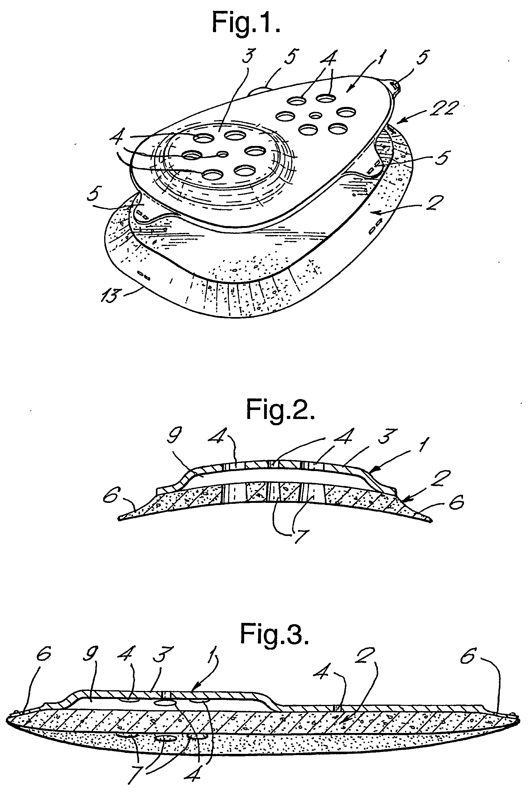
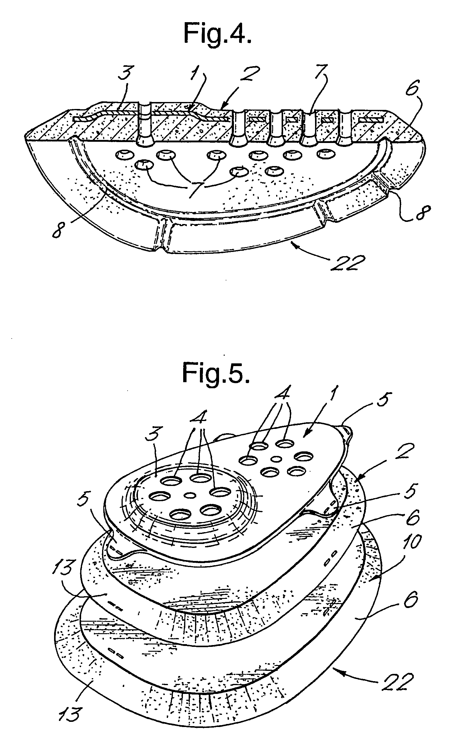
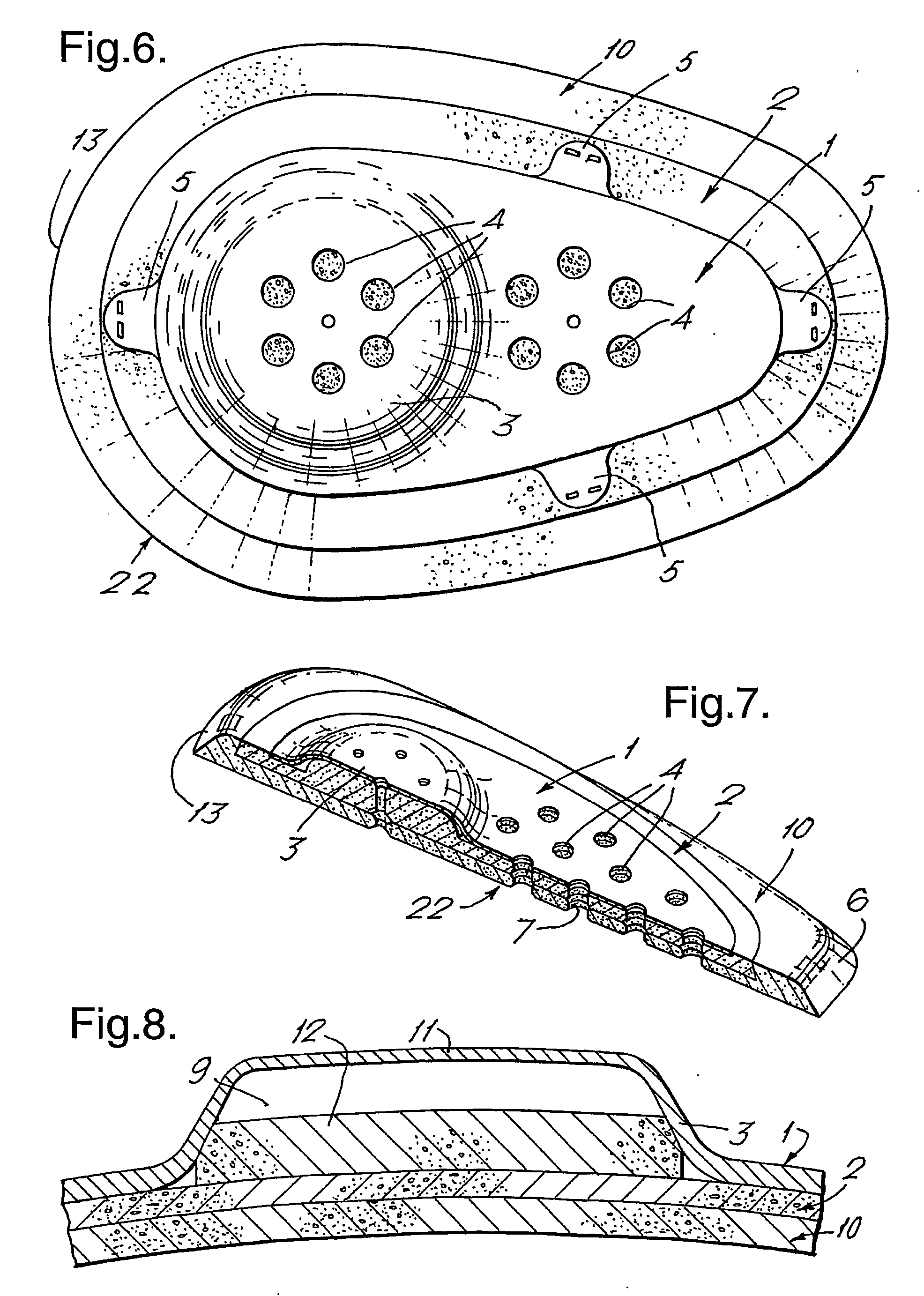
[0031] The first example of protective pad comprises a substantially rigid layer 1 and a layer of dense closed-cell resilient foam material 2. The substantially rigid layer 1 includes a projecting boss 3 and arrays of ventilation holes 4. The substantially rigid layer 1 also includes thin fixing lugs 5 projecting from its periphery. The dense closed-cell resilient foam layer 2 includes a chamfered outer peripheral region 6 and ventilation holes 7 which align with the ventilation holes 4 in the rigid layer 1. The ventilation holes 7 may be of larger diameter than the ventilation holes 4 or may be tapered as shown in FIGS. 2 and 3.

[0032] The substantially rigid layer 1 may be formed from polyurethane or polypropylene and the closed cell resilient foam layer 2 may be formed from polyurethane or, for example EVA foam. The two layers may be bonded together using an adhesive but in this example they are stitched together through the fixing lugs 5. The periphery of the substantially rigid...


PUM


Abstract

When people fall they tend to fall on their side. This can lead to them breaking their femur particularly at the head around the trochantheric region. The head of the femur includes a portion called the greater trochanter which projects outwards and which is covered by very little flesh. A pad for use in protecting trochantheric region of the body comprises at least two separate layers, a substantially rigid layer, and a layer of dense, closed-cell resilient foam material. The substantially rigid layer includes a protecting boss which, in use, is located in the region of the greater trochanter to increase the spacing between the outside of the rigid layer and the greater trochanter. Preferably, the layer of closed-cell foam material extends over a greater area than the substantially rigid layer so that the periphery of the rigid layer lies entirely within the periphery of the foam layer.

Description

FIELD OF THE INVENTION [0001] When people fall, particularly the elderly and frail or those less active whilst recovering from surgery, for example, they tend to fall on their side. This can lead to them breaking their femur particularly at the head around the trochantheric region. The head of the femur includes a portion called the greater trochanter which projects outwards and which is covered by very little flesh. When falling sideways onto this region, the femur can strike the ground and with very little flesh to cushion the impact, the femur is subjected to a considerable force which may be equivalent to as much as five times body weight acting on the greater trochanter. Since the inner end of the head of the femur is held substantially rigidly by the pelvis, the femur itself cannot move inwards to absorb the shock and this leads to the breakage of the femur in the trochantheric region. DISCUSSION OF THE PRIOR ART [0002] Many proposals have been made to provide protection for t...

Claims


Application Information

Patent Timeline
Patent Type & Authority Applications(United States)
IPC IPC(8): A41D13/05A41D31/00
CPCA41D13/0158A41D13/0506A41D13/0568A41D13/0575A41D13/0581A41D31/285
Inventor FULFORD, ROBERTTORRENS, GEORGE
Owner REMPLOY
Why Eureka
Try Eureka