Sequential selective integration of sensor data

a sensor data and selective integration technology, applied in the field of combining or fusing data from sensors, can solve the problems of not updating the estimate of characteristic correctly, not convergently, and common estimation of characteristic that cannot be known with certainty,

Inactive Publication Date: 2005-10-20
EVOLUTION ROBOTICS
View PDF2 Cites 213 Cited by
  • Summary
  • Abstract
  • Description
  • Claims
  • Application Information

AI Technical Summary

Benefits of technology

[0015] The VSLAM technologies disclosed herein can advantageously be applied to autonomous robots and to non-autonomous robots. For example, the VSLAM technologies can be used with a manually-driven vehicle, such as a remotely-controlled vehicle for bomb detection. By way of example, the VSLAM technologies can be advantageously used in a remote-control application to assist an operator to navigate around an environment. In one embodiment, a vehicle can include various operational modes, such as a mode for manual control of the vehicle and another mode for an autonomous control of the vehicle. For example, the vehicle can be manually-driven during an initial mapping stage, and then later, the vehicle can be configured for autonomous control. In another embodiment, the VSLAM technnologies can be used by a scout to create a map of the region. The scout can correspond to, for example, a person or another animal, such as a dog or a rat. The VSLAM used by the scout can be coupled to a video camera carried by the scout to observe the environment and to a dead reckoning device, such as an odometer, a pedometer, a GPS sensor, an inertial sensor, and the like, to measure displacement. The map generated by the scout can be stored and later used again by the scout or by another entity, such as by an autonomous robot. It will be understood that between the generation of the map by the scout and the use of the map by another entity, there can be additional processing to accommodate differences in visual sensors, differences in the installed height of the visual sensor, and the like.
[0016] Robots can be specified in a variety of configurations. In one example, a robot configuration includes at least one dead reckoning sensor and at least one video sensor. Another name for dead reckoning is “ded” reckoning or deduced reckoning. An example of a dead reckoning sensor is a wheel odometer, where a sensor, such as an optical wheel encoder, measures the rotation of a wheel. The rotation of wheels can indicate distance traveled, and a difference in the rotation of wheels (such as a left side wheel and a right side wheel) can indicate changes in heading. With dead reckoning, the robot can compute course and distance traveled from a previous position and orientation (pose) and use this information to estimate a current position and orientation (pose). While relatively accurate over relatively short distances, dead reckoning sensing is prone to drift over time. It will be understood that the information provided by a dead reckoning sensor can correspond to either distance, to velocity, or to acceleration and can be converted as applicable. Other forms of dead reckoning can include a pedometer (for walking robots), measurements from an inertial measurement unit, optical sensors such as those used in optical mouse devices, and the like. Disadvantageously, drift errors can accumulate in dead reckoning measurements. With respect to a wheel odometer, examples of sources of drift include calibration errors, wheel slippage, and the like. These sources of drift can affect both the distance computations and the heading computations.

Problems solved by technology

The problem of estimating a characteristic that cannot be known with certainty is common.
However, a disadvantage of the standard particle filter is that it often fails to update the estimate of characteristic correctly, and, often, if the error in the initial estimate is large, the estimate converges relatively slowly, or not at all.
This weakness is due to the limited number of samples used to approximate the relevant probability distributions; namely, the samples tend to cluster more than is appropriate in regions where the density function is relatively large.
A conventional technique to reduce this limitation is to use a relatively large number of samples (particles), which disadvantageously results in a large computational requirement on the filtering process.
In addition, the statistical properties of the measurements are typically not known with accuracy, which can cause the performance of particle filter to break down.
In particular, if a robot is lifted and moved to a new location without receiving an indication that such motion has occurred, it has been exposed to what is called “kidnapping.”.
However, immediately after the kidnapping, this estimate is very likely to be wrong because that most conventional methods of data fusion are not able to recover the pose in a short amount of time.
An important weakness of the methods described in Montemerlo, et al., id. is that if the robot is kidnapped a relatively short time before the map is expanded (i.e., a new feature, such as a new landmark, is added to the map), then it will be relatively difficult for the robot to recover and fully correct the map.
A second disadvantage of the methods described in reference 4 lies in the so-called “landmarks” that form the basis for its map.
While relatively accurate over relatively short distances, dead reckoning sensing is prone to drift over time.
Disadvantageously, drift errors can accumulate in dead reckoning measurements.

Method used


Image

  • Sequential selective integration of sensor data
  • Sequential selective integration of sensor data
  • Sequential selective integration of sensor data

Examples


Embodiment Construction

[0056] Although particular embodiments are described herein, other embodiments, including embodiments that do not provide all of the benefits and features set forth herein, will also be apparent to those of ordinary skill in the art.

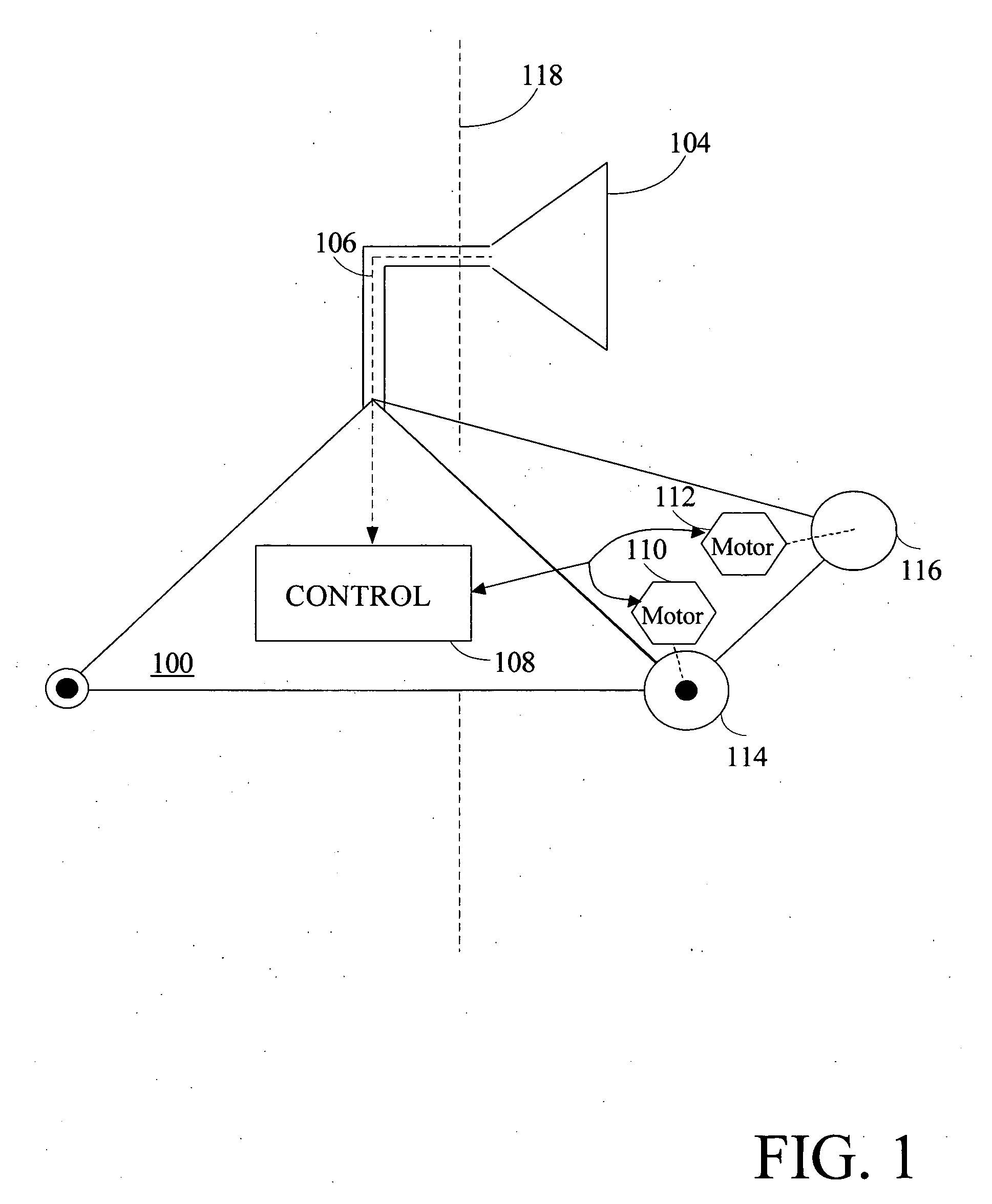
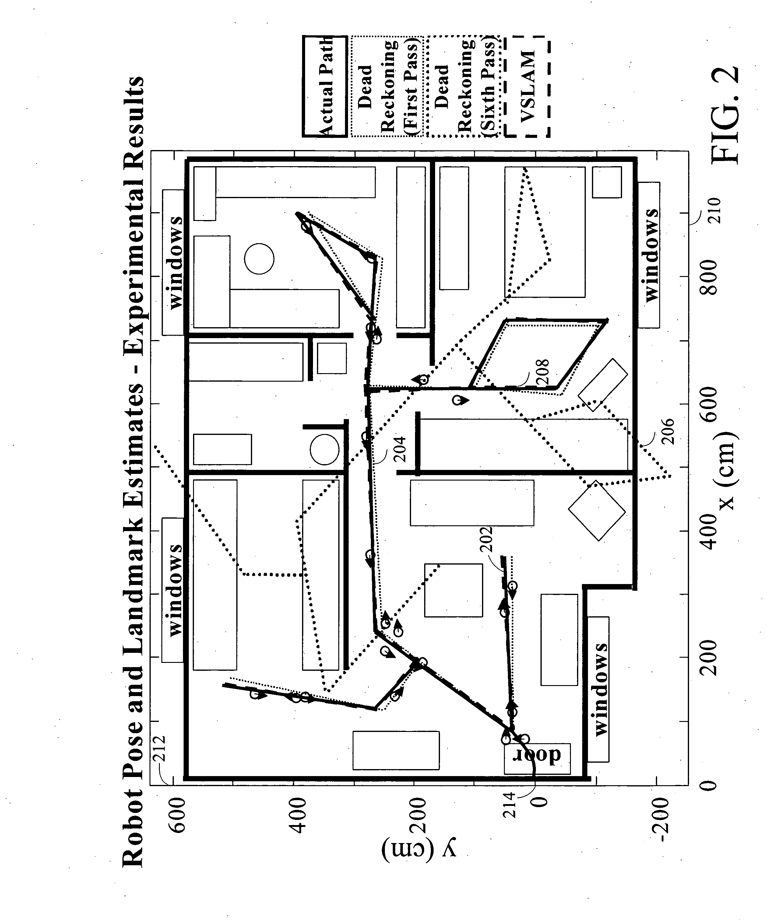
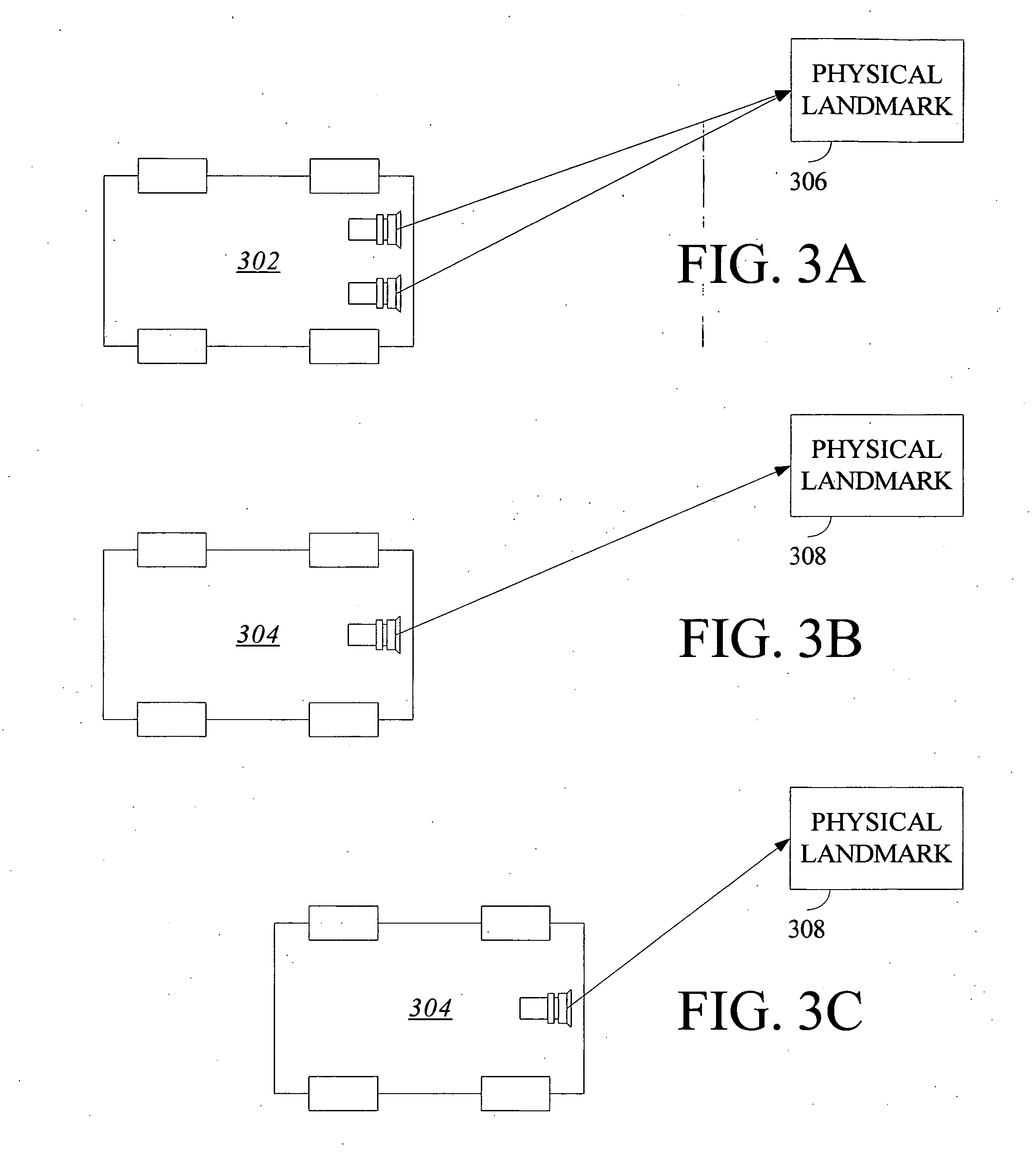
[0057] An example of an embodiment of the method advantageously uses one or more visual sensors and one or more dead reckoning sensors to process Simultaneous Localization and Mapping (SLAM). The combination of SLAM with visual sensors will hereafter be referred to as VSLAM. Advantageously, such visual techniques can be used by a vehicle, such as a mobile robot, to autonomously generate and update a map. In one embodiment, VSLAM is advantageously used by a portion of a vehicle, such as by an arm, leg, hand, or other appendage of a vehicle. In contrast to localization and mapping techniques that use laser rangefinders or other range-based devices or sensors, the visual techniques are economically practical in a wide range of applications and can be used ...


PUM


Abstract

This invention is generally related to sequential methods and apparatus that permit the measurements from a plurality of sensors to be combined or fused in a robust manner. For example, the sensors can correspond to sensors used by a mobile device, such as a robot, for localization and/or mapping. The measurements can be fused for estimation of a measurement, such as an estimation of a pose of a robot.

Description

RELATED APPLICATION [0001] This application claims the benefit under 35 U.S.C. § 119(e) of U.S. Provisional Application No. 60 / 544,486, entitled “METHODS FOR ROBUST SENSOR FUSION,” filed Feb. 13, 2004, the entirety of which is hereby incorporated by reference.Appendix A [0002] Appendix A, which forms a part of this disclosure, is a list of commonly owned copending U.S. patent applications. Each one of the applications listed in Appendix A is hereby incorporated herein in its entirety by reference thereto. BACKGROUND [0003] 1. Field of the Invention [0004] The invention generally relates to combining or fusing data from sensors. In particular, the invention relates to robust techniques for a robot of combining data that may include potentially unreliable data. [0005] 2. Description of Related Art [0006] The problem of estimating a characteristic that cannot be known with certainty is common. For example, if sensor measurements with known statistical properties and correlated with the...

Claims


Application Information

Patent Timeline
Patent Type & Authority Applications(United States)
IPC IPC(8): G05D1/02G06F15/00
CPCG05D1/024G05D1/0272G05D1/0246G05D1/0242G05D1/0248G05D1/0274
Inventor KARLSSON, LARS NIKLAS
Owner EVOLUTION ROBOTICS
Why Eureka
Try Eureka