Motor frame cooling with hot liquid refrigerant and internal liquid

a technology of hot liquid refrigerant and motor frame, which is applied in the direction of refrigeration components, lighting and heating apparatus, domestic cooling apparatus, etc., can solve the problem that single-phase cooling cannot be completely removed, and achieve the effect of enhancing both the two-phase and the single-phase heat transfer arrangemen

Inactive Publication Date: 2005-10-27
UT BATTELLE LLC
View PDF26 Cites 29 Cited by
  • Summary
  • Abstract
  • Description
  • Claims
  • Application Information

AI Technical Summary

Benefits of technology

[0005] The single phase cooling cannot be totally removed even in a two-phase cooling system. For example, in a motor the heat loss produced in the stator winding still needs to go through a single-phase heat transfer (i.e. thermal conduction) before reaching to the two-phase cooling zone. This invention presents a method that can enhance both the two-phase and the single-phase heat transfer arrangements.

Problems solved by technology

The pressure that the water jacket can take is not as high as what a certain refrigerant such as R134a takes, as well as potential porosity problems in aluminum castings causing leaks under high pressure.
The single phase cooling cannot be totally removed even in a two-phase cooling system.

Method used


Image

  • Motor frame cooling with hot liquid refrigerant and internal liquid
  • Motor frame cooling with hot liquid refrigerant and internal liquid
  • Motor frame cooling with hot liquid refrigerant and internal liquid

Examples


Embodiment Construction

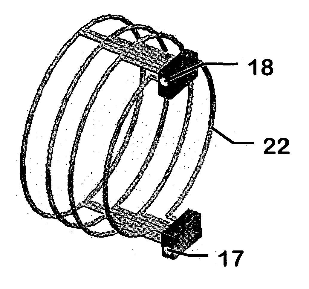
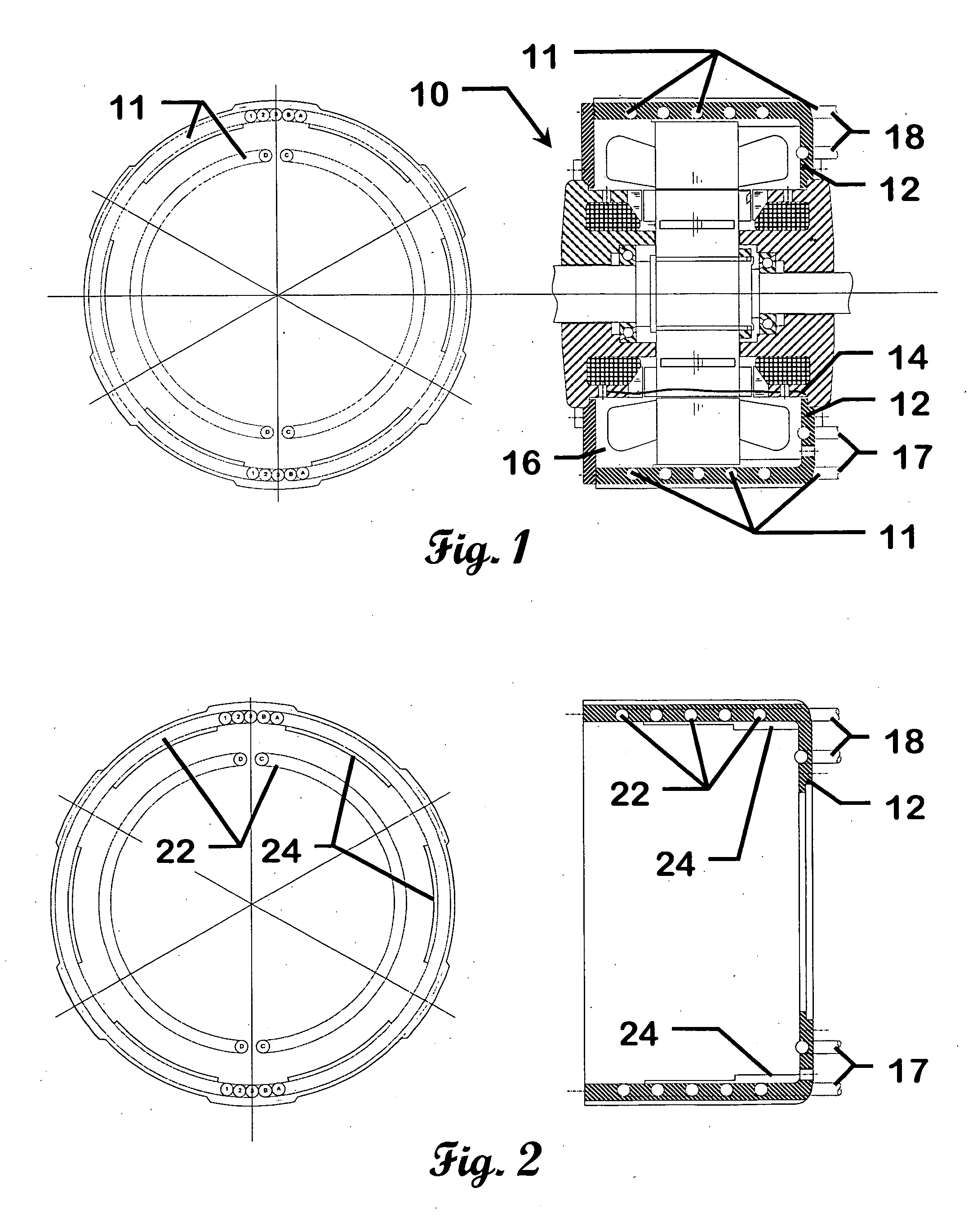
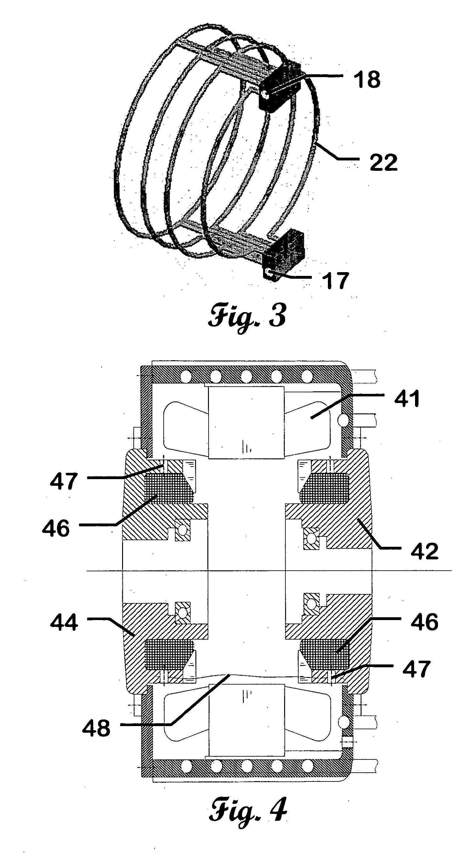
[0018]FIG. 1 shows an embodiment of the invention using tubes 11 cast in a frame 12 and internal liquid level 14 inside electric machine 10 for combined two-phase and single-phase cooling. Metal tubes withstand the high pressures required by the hot liquid refrigerant flowing in the frame 12. An internal liquid 16 such as a transmission or lubrication oil is filled at the bottom of the frame 12. Hot liquid refrigerant 17 enters the electric machine 10 from a floating refrigerant loop (not shown) as described in co-pending U.S. patent application No. 60 / 565,461 filed Apr. 26, 2004, herein incorporated by reference, and hot vapor refrigerant 18 exits the electric machine 10 returning to the floating refrigerant loop. The hot vapor refrigerant 18 that exits the electric machine 10 can be a mixture of refrigerant vapor and liquid depending on the heat load imposed by the electric machine. The floating refrigerant loop can be a stand-alone loop having a dedicated pump and condenser. Or, ...


PUM


Abstract

This invention presents the device and method for cooling electric machines with hot liquid refrigerant in a floating refrigerant loop and using an internal liquid such as oil for enhancing the cooling effects. The electric machine cooling apparatus has at least one refrigerant tube disposed in the electric machine. The refrigerant tube is in thermal communication with the electric machine. An internal liquid is disposed inside the frame of the electric machine. The internal liquid is in thermal communication with the electric machine and at least one refrigerant tube. The refrigerant is at least partially a hot liquid refrigerant supplied from a floating refrigerant loop.

Description

CROSS-REFERENCE TO RELATED APPLICATIONS [0001] This application claims priority to U.S. Provisional Patent Application 60 / 565,461 filed Apr. 26, 2004, and is herein incorporated by reference. This application is related to U.S. patent application Ser. No. 10 / 926,205 filed Aug. 25, 2004, and is herein incorporated by reference.STATEMENT REGARDING FEDERALLY SPONSORED RESEARCH [0002] This invention was made with United States Government support under Contract No. DE-AC05-00OR22725 between the United States Department of Energy and U.T. Battelle, LLC. The United States Government has certain rights in this invention.BACKGROUND OF THE INVENTION [0003] For vehicles using electric motors and power electronic inverters, two-phase cooling with the coolant changed from the liquid phase to the vapor phase is far more effective than using single-phase such as liquid to liquid heat transfer. The significant latent heat associated with the two phase heat transfer is the reason for making two-phas...

Claims


Application Information

Patent Timeline
Patent Type & Authority Applications(United States)
IPC IPC(8): F25B31/00F25D23/12H02K5/20H02K9/19
CPCH02K9/19H02K5/20H02K5/203H02K9/20
Inventor HSU, JOHN S.AYERS, CURTIS W.COOMER, CHESTER
Owner UT BATTELLE LLC
Why Eureka
Try Eureka