Cutting anvil and method

a cutting anvil and cutting method technology, applied in the field of cutting anvils, can solve the problems of low cutting accuracy, low cutting accuracy, and inability to cut the backing film, etc., and achieve the effect of convenient cutting

Inactive Publication Date: 2005-10-27
THE BOEING CO
View PDF32 Cites 6 Cited by
  • Summary
  • Abstract
  • Description
  • Claims
  • Application Information

AI Technical Summary

Benefits of technology

[0006] The foregoing needs are met, to a great extent, by the present invention, wherein in some embodiments an anvil that facilitates cutting ply material is provided.

Problems solved by technology

A disadvantage associated with conventional anvils is the relatively high precision required to install and prepare them for use.
Minor deviations in height adjustment may result in incomplete cuts of the ply material or cutting of the backing film.
As the backing film is removed, torn backing film may remain on the ply, may fowl the ply placement head, and / or may lead to breakage of the backing film.
Another disadvantage associated with conventional anvils is that essentially any contact between the cutting tool and the anvil while setting up the cutting assembly or during use may result in damage to the cutting tool and / or the anvil.
Even apparently minor damage to the cutting tool may produce unsatisfactory cutting performance and thus, require cutting tool replacement or regrinding.
Damage to the anvil typically manifests itself as score marks.
These score marks may cause cutting problems resulting from an altered cutting surface and generally tend to increase the drag of the tape as the tape is fed through the tape laying head.
Down time associated with replacement of the cutting tool and / or anvil wastes resources.

Method used


Image

  • Cutting anvil and method
  • Cutting anvil and method
  • Cutting anvil and method

Examples


Embodiment Construction

[0021] The present invention provides, in some embodiments, a cutter assembly, an anvil for the cutter assembly, and a method of generating the anvil. In an embodiment, the invention provides for an anvil for cutting a backed ply material.

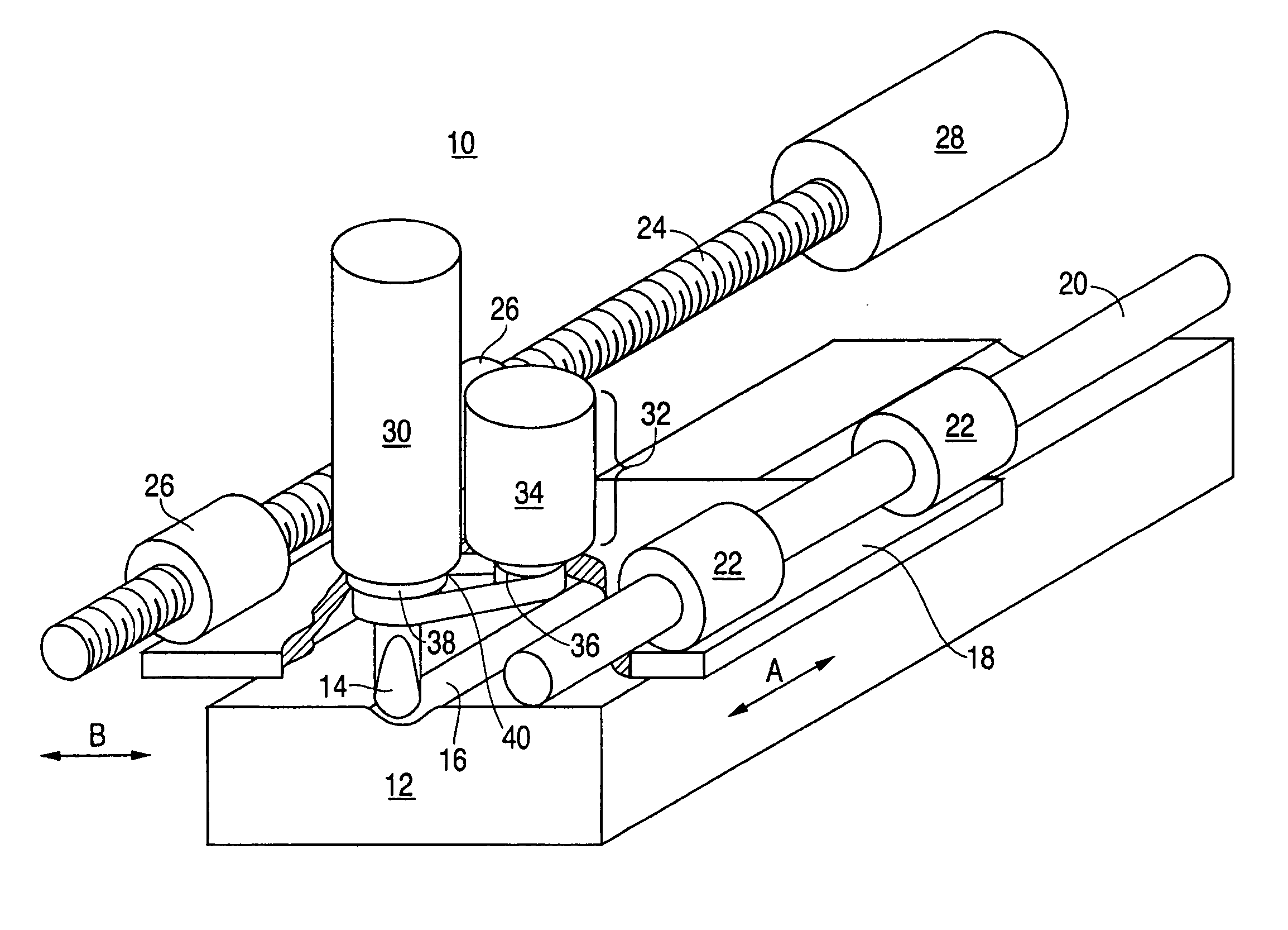
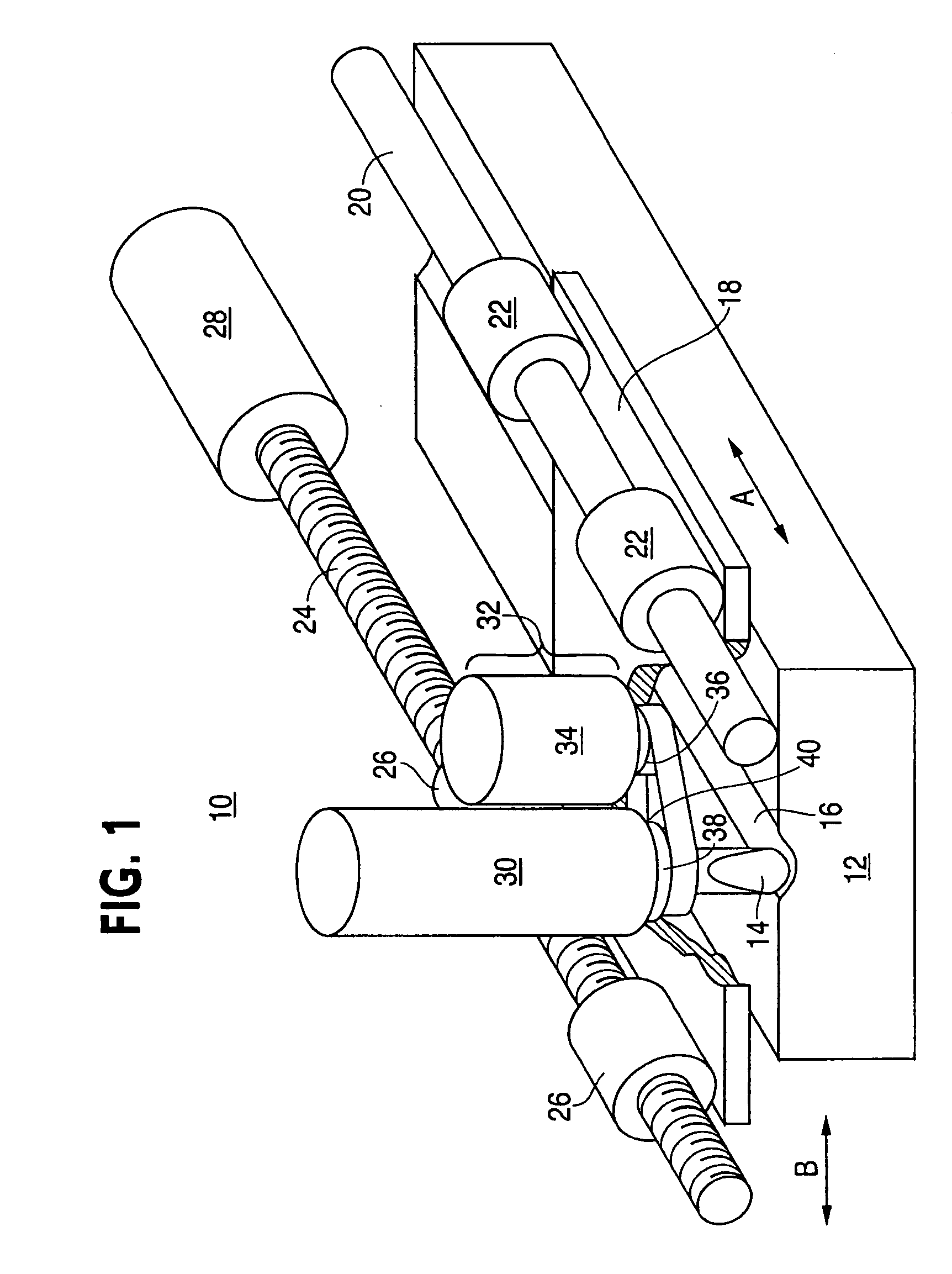
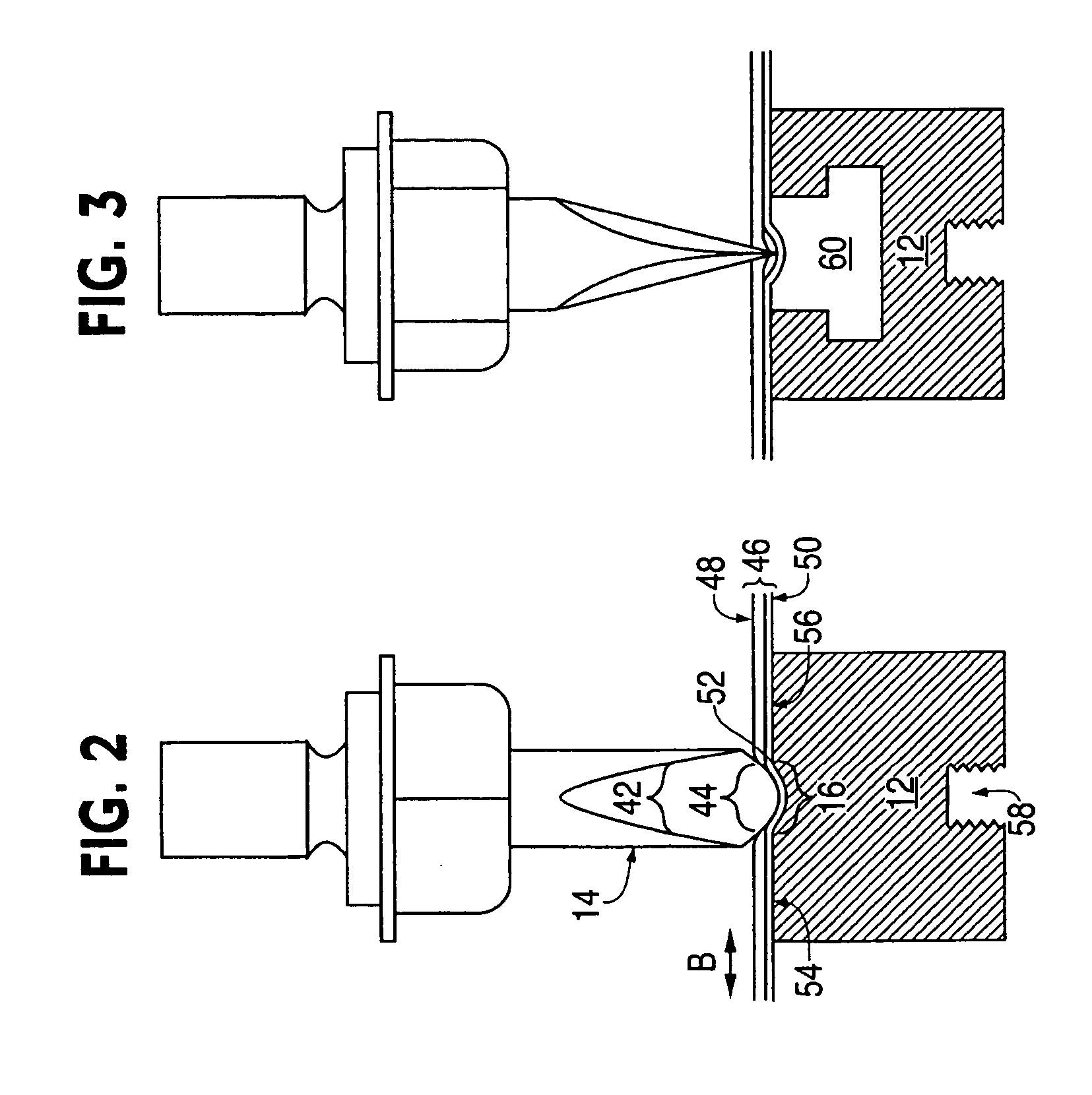
[0022] The invention will now be described with reference to the drawing figures, in which like reference numerals refer to like parts throughout. As shown in FIG. 1, a cutting assembly 10 includes an anvil 12 and a stylus 14. The anvil 12 and the stylus 14 are juxtaposed in co-operative alignment to facilitate cutting of ply material. That is, the anvil 12 provides support for the ply material and thereby facilitates the cutting action of the stylus 14. In various embodiments of the invention, the anvil 12 includes a groove 16 cooperatively aligned with the stylus 14. In a particular embodiment shown in FIG. 1, the groove 16 is coincidental with a path of the stylus 14. In this regard, the stylus 14 is mounted to a platform 18. Movement of this p...


PUM

PropertyMeasurementUnit
pressureaaaaaaaaaa
polymericaaaaaaaaaa
molecular weightaaaaaaaaaa

Abstract

To cut a backed ply material with an ultrasonic blade, an anvil is utilized to provide support. The backed ply material travels in a first direction, the ultrasonic blade includes a tip, and the ultrasonic blade is operable to travel along a path. This path is oriented in a transverse manner relative to the first direction. The anvil includes a rigid base for securing the anvil to a cutting assembly and a surface coinciding with the path. The surface is secured to the base. The anvil further includes a groove disposed upon the surface. This groove is in cooperative alignment with the tip.

Description

FIELD OF THE INVENTION [0001] The present invention generally relates to an anvil for supporting cuts in sheet and roll stock. More particularly, the present invention pertains to an improved anvil for supporting cuts in composite ply material and its method of use. BACKGROUND OF THE INVENTION [0002] Composite structures are typically constructed from multiple layers or plies. These plies may include a variety of materials such as carbon fiber, various other fibers, metal foils, and the like. In addition, the plies may be pre-impregnated with a resin and are often dispensed from a roll or spool. In roll form, the ply material is referred to as “tape” and typically includes a paper backing film. This backing film generally prevents pre-impregnated ply material (prepreg) from adhering to itself and aids in handling the ply as the ply is applied to the tool and the layup. In particular, at the beginning and end of each ply placement, the ply material is generally cut to match the profi...

Claims


Application Information

Patent Timeline
Patent Type & Authority Applications(United States)
IPC IPC(8): B23D21/14B26D1/04B26D5/08B26D7/08B26D7/20
CPCB26D1/025B26D1/045B26D3/06B26D7/20B26D7/086Y10T83/8745Y10T83/97Y10T83/4841Y10T83/9312Y10T83/0304Y10T83/687
Inventor EVANS, RICHARD B.
Owner THE BOEING CO
Why Eureka
Try Eureka