Leak container for fuel dispenser

a technology for leakage containers and fuel dispensers, applied in the direction of liquid transfer devices, liquid handling, packaging goods types, etc., can solve the problem that unauthorised persons cannot gain access to the leakage collection chamber

Active Publication Date: 2005-10-27
GILBARCO
View PDF41 Cites 15 Cited by
  • Summary
  • Abstract
  • Description
  • Claims
  • Application Information

AI Technical Summary

Benefits of technology

[0009] The present invention relates to a leak collection chamber inside a fuel dispenser housing. In one embodiment, the leak collection chamber is placed inside a fuel handling components area of the fuel dispenser. The leak collection chamber collects any leaked fuel from inside the fuel dispenser to prevent such fuel from reaching the environment. The fuel dispenser may be additionally equipped with a slanted collection plate to direct leaked fuel into the leak collection chamber if the leak collection chamber does not include the same internal size as the housing of the fuel dispenser.
[0010] In one embodiment, a scale is provide underneath the leak collection chamber to measure the weight of the chamber. The weight of the chamber is communicated electronically to a control system inside the fuel dispenser. Using the weight measurement, the control system can determine the fluid level inside the leak collection chamber using a conversion factor between weight and fluid level. In this manner, the control system has knowledge of when the liquid level inside the leak collection chamber has exceeded a threshold level so that the control system can alert service personnel, via signals and alarms, to empty the leak collection chamber before it overflows. In another embodiment, a liquid level sensor placed inside the leak collection chamber is communicated to the control system to indicate the fluid level inside the leak collection chamber.
[0011] The control system may also measure the liquid level in the leak collection chamber are various point in time to determine the speed or ra

Problems solved by technology

If the increase in collection of leaks exceeds a threshold increase rate, this may be indicative of a catastrophic leak inside the fuel

Method used


Image

  • Leak container for fuel dispenser
  • Leak container for fuel dispenser
  • Leak container for fuel dispenser

Examples


Embodiment Construction

[0023] The embodiments set forth below represent the necessary information to enable those skilled in the art to practice the invention and illustrate the best mode of practicing the invention. Upon reading the following description in light of the accompanying drawing figures, those skilled in the art will understand the concepts of the invention and will recognize applications of these concepts not particularly addressed herein. It should be understood that these concepts and applications fall within the scope of the disclosure and the accompanying claims.

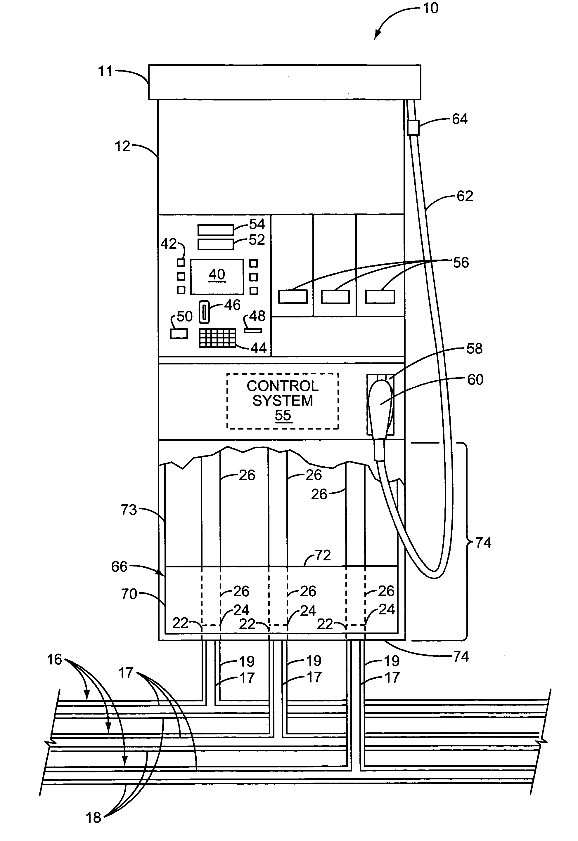
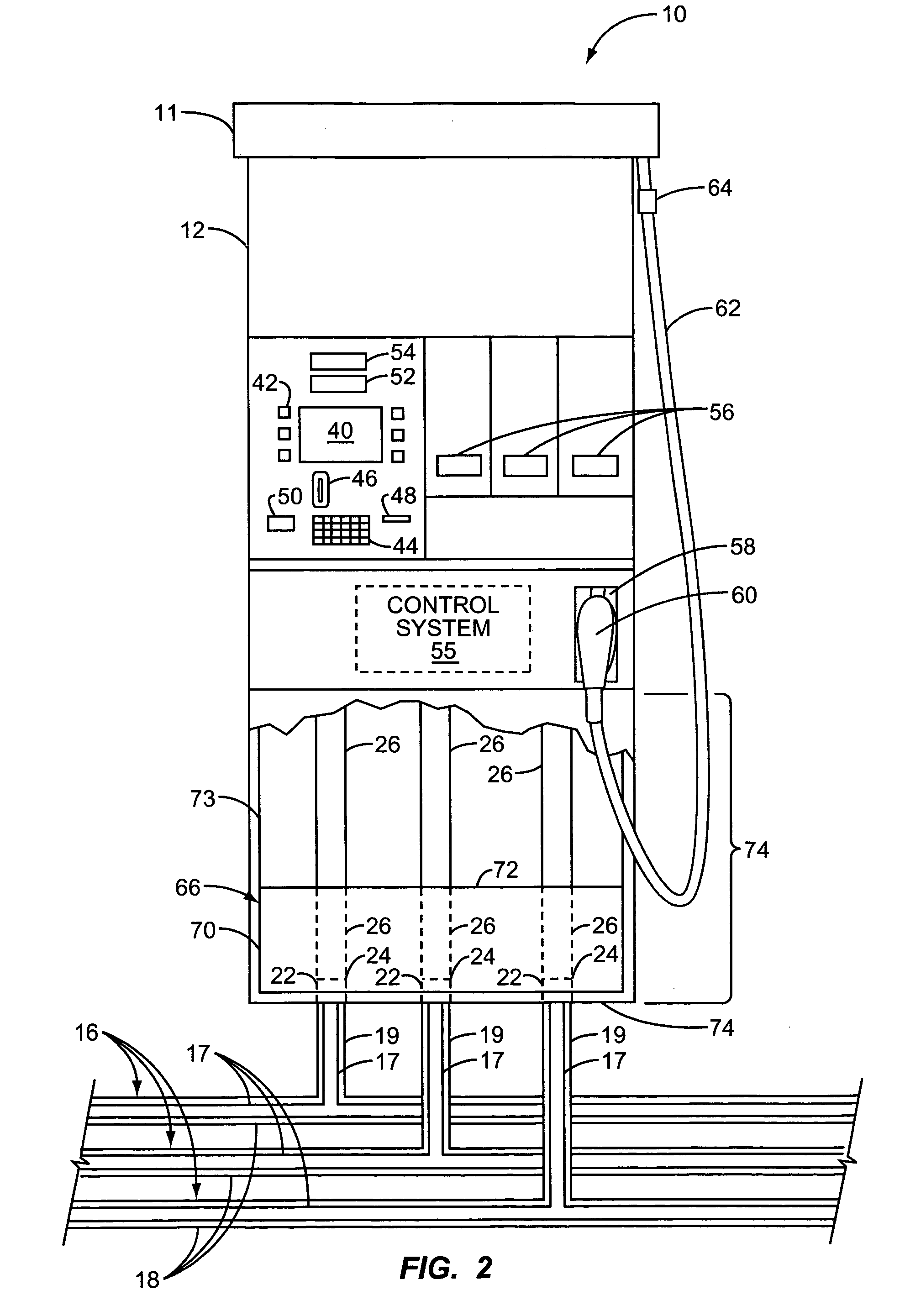
[0024] The present invention is a fuel dispenser that eliminates the need for a fuel dispenser sump located underneath the ground. The present invention provides a leak containment chamber inside the fuel dispenser that collects any leaked fuel from the fuel piping inside the fuel dispenser.

[0025] In FIG. 2, an exemplary fuel dispenser 10 is illustrated with some similar characteristics of the fuel dispenser 10 in FIG. 1. The f...


PUM

PropertyMeasurementUnit
Weightaaaaaaaaaa
Areaaaaaaaaaaa
Levelaaaaaaaaaa

Abstract

A leak collection chamber is provided inside the housing of a fuel dispenser. The leak collection chamber collects any leaked fuel from fuel handling components inside the fuel dispenser so that the fuel does not leak to the environment. The leak collection chamber can be removed form the fuel dispenser for evacuation. The control system inside the fuel dispenser can determine the liquid level inside the leak containment chamber and generate signals and alarms if the liquid level exceeds a threshold liquid level value and/or the rate of increase in liquid level exceeds a threshold liquid level increase value. The control system can alert service personnel and/or other systems of the leak collection chamber liquid level. Further, the control system and/or other systems shut down the submersible turbine pump that services the fuel dispenser with fuel in response to catastrophic leak condition.

Description

FIELD OF THE INVENTION [0001] The present invention relates to providing a fluid containment chamber within a fuel dispenser to collect leaked fluid, including fuel, and / or for a fuel dispenser that does not require a fuel dispenser sump. BACKGROUND OF THE INVENTION [0002] As illustrated in FIG. 1, fuel dispensers 10 are installed in service stations on islands 14. The islands 14 are footprints that are designed to receive a fuel dispenser housing 12. The islands 14 are typically constructed out of cement slabs and have pre-run fuel piping conduits that are run underneath the ground to submersible turbine pumps (not shown) that are coupled to underground storage tanks (not shown) containing fuel. The fuel is pumped from the underground storage tanks to the fuel dispensers 10 via the fuel piping conduit. [0003] As shown in FIG. 1, the fuel piping conduit consists of a main fuel piping conduit 16 that carries fuel underneath each of the fuel dispensers 10. A separate main fuel piping ...

Claims


Application Information

Patent Timeline
IPC IPC(8): B67D7/32B67D7/84
CPCB67D7/3209B67D7/84B67D7/3218B67D7/04Y10T137/0452Y10T137/5762Y10T137/8342
Inventor HUTCHINSON, RAY J.MCSPADDEN, JOHN S.
Owner GILBARCO
Why Eureka
Try Eureka