Adjustable router guide template assembly

a router guide and template technology, applied in the field of router guides, to achieve the effect of easy interchange and minimal effor

Inactive Publication Date: 2005-10-27
OBRIEN VINCENT E
View PDF12 Cites 34 Cited by
  • Summary
  • Abstract
  • Description
  • Claims
  • Application Information

AI Technical Summary

Benefits of technology

[0009] Accordingly, by utilizing the support plate collar and contact wall of the base member to determine the target cut, the present invention can be applied to workpieces having a width much smaller than the diameter of the router base. This is a significant problem with most router guides which utilize the outer circumferential edge of the router base as a contact stop. Moreover, the adjustable guide assembly of the present invention enables a much more efficient set-up and operation to perform standard plough, mortise and tenon cuts. Unlike the current designs, should the length and / or width of the cut require changing, the simple adjustments are performed as opposed to the more complicated setting and resetting of the current router guides.
[0013] A bushing plate may also be positioned in the bit passage of the base member, as opposed to the end bushings, to further define the shape and size of the target cut. These plates provide predetermined passage shapes that receive the cutting bit therein. In this manner, the bushing plates can be easily interchanged with minimal effort.

Problems solved by technology

This is a significant problem with most router guides which utilize the outer circumferential edge of the router base as a contact stop.

Method used


Image

  • Adjustable router guide template assembly
  • Adjustable router guide template assembly
  • Adjustable router guide template assembly

Examples


Embodiment Construction

[0028] While the present invention will be described with reference to a few specific embodiments, the description is illustrative of the invention and is not to be construed as limiting the invention. Various modifications to the present invention can be made to the preferred embodiments by those skilled in the art without departing from the true spirit and scope of the invention as defined by the appended claims. It will be noted here that for a better understanding, like components are designated by like reference numerals throughout the various figures.

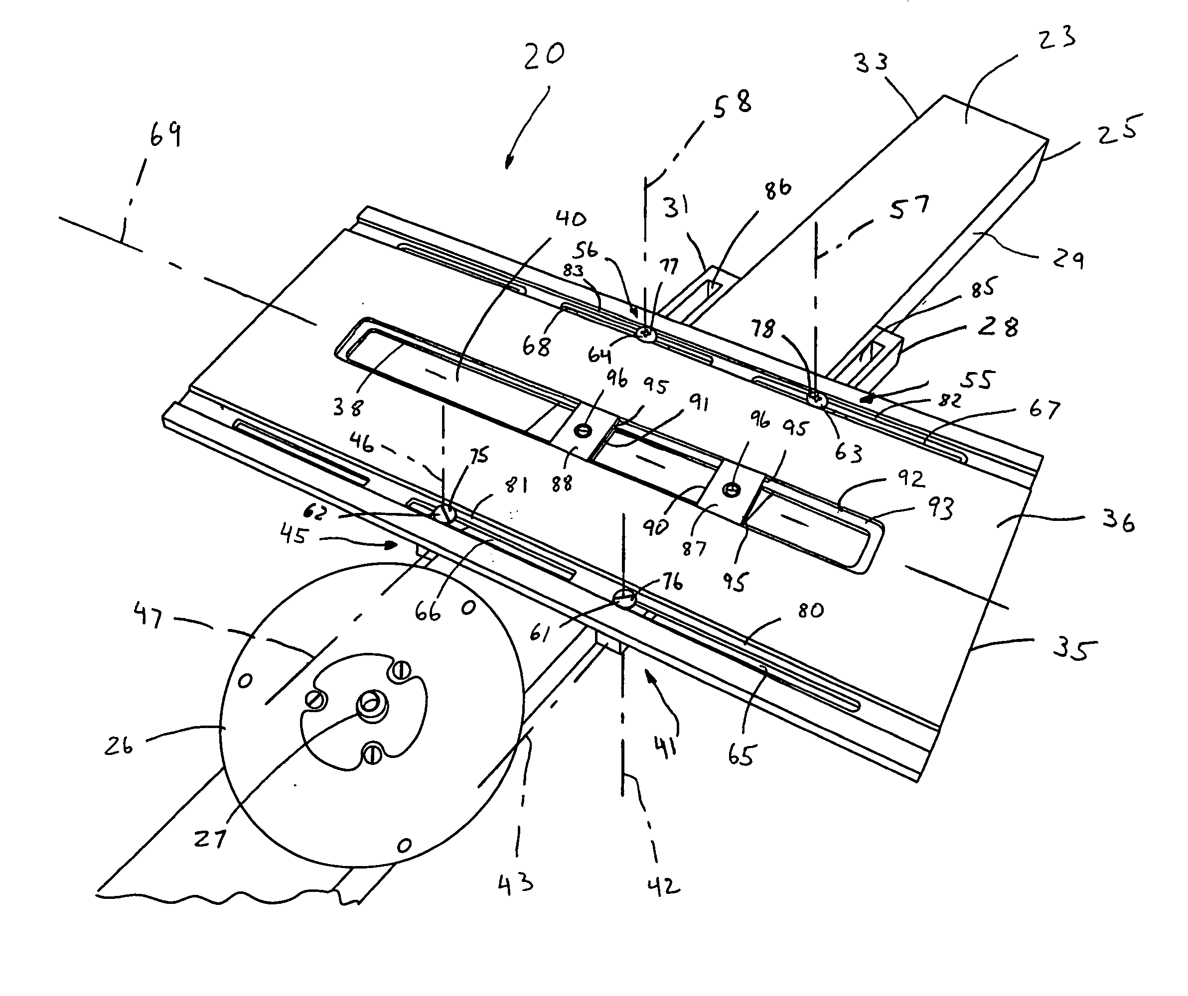
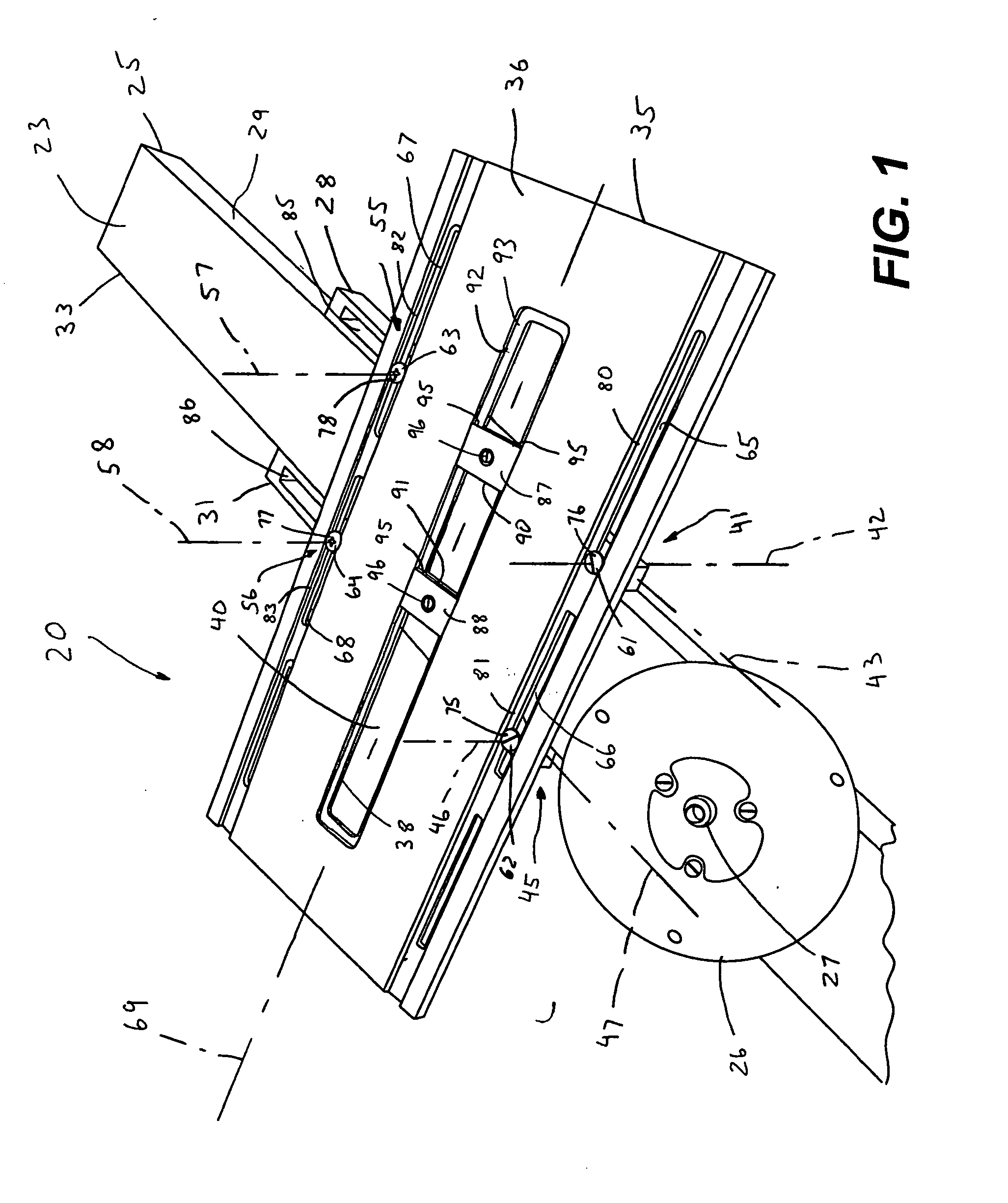
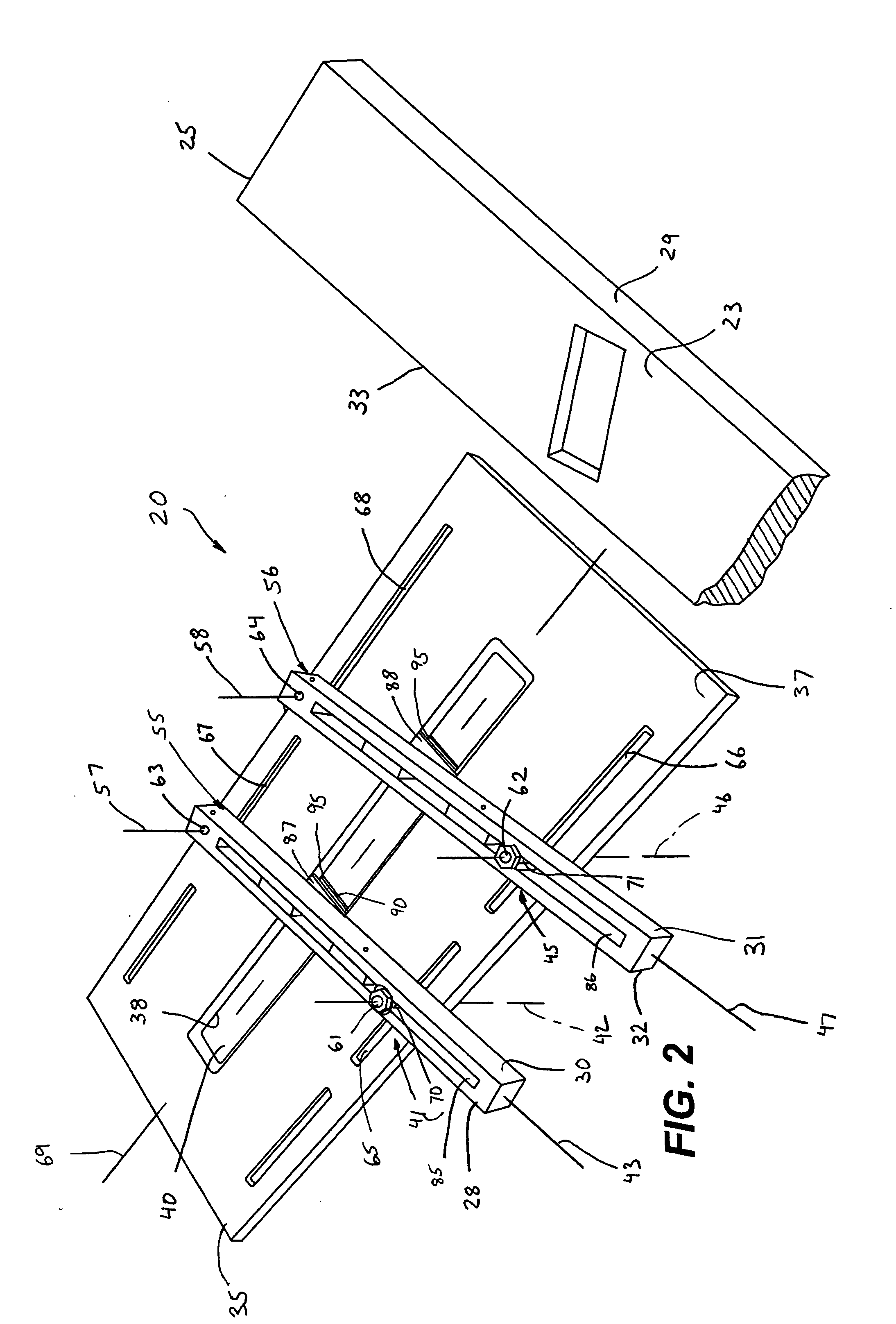
[0029] Referring now to FIGS. 1-5, the present invention provides an adjustable guide assembly, generally designated 20, to guide a cutter bit 21 of a tool device 22 (FIG. 5) about a cutting surface 23 of a workpiece 25. The application of the guide assembly 20 is particularly suitable for plough and mortise cuts, but may also be employed to fabricate dados and rabbet, etc. In this instance, the tool device 22 is preferably a han...


PUM


Abstract

An adjustable guide assembly to guide a cutter bit of a tool device about a cutting surface of a workpiece. The guide assembly includes an elongated first guide rail having a first abutting surface adapted to abut a first side wall of the workpiece, and a second guide rail spaced-apart from the first guide rail, and having a second abutting surface adapted to abut a second side wall of the workpiece. A base member is positioned over the first and second guide rails, and includes a tool support surface and an opposed workpiece support surface. The base member includes a contacting wall defining a bit passage therethrough. A first and second interconnection assembly is configured to releasably lock the first and second guide rail, respectively, to the base member in a manner enabling the first guide rail to pivot about a first axis substantially perpendicular to a longitudinal axis of the first guide rail, and the second guide rail to pivot about a second axis substantially perpendicular to a longitudinal axis of the second guide rail, respectively. Further, the first interconnection assembly and the second interconnection assembly enable the first guide rail and the second guide rail to slide along the base member along respective paths adjacent to the bit passage. The first guide rail and the second guide rail are adjusted to abut the workpiece first side wall and the workpiece second side wall in a manner releasably positioning a targeted cutting region of the workpiece cutting surface in the bit passage.

Description

FIELD OF THE INVENTION [0001] The present invention relates to router guides, and more particularly, relates to router guides with template assemblies to guide a router along predefined cutting paths. BACKGROUND OF THE INVENTION [0002] Router devices are often employed for decorative and constructive applications in the woodworking trade. In decorative applications, routers and their corresponding router bits are used for both linear and curvilinear side-cuts, such as dadoes, and for decorative grooves and channels. For constructive applications, the router is applied more or less for straight cuts along lengthwise dimensions and / or widthwide dimensions of a workpiece to fashion ploughs, mortises and / or the two-step routing of tenons and the like. For example, in the construction of wooden ladders, router devices and their corresponding router bits are applied to create mortise cuts in the ladder side supports, they are applied to created tenons cuts in the step portions of the ladd...

Claims


Application Information

Patent Timeline
Patent Type & Authority Applications(United States)
IPC IPC(8): B23Q9/00B27C5/10B27M3/12
CPCB27M3/12B27C5/10
Inventor O'BRIEN, VINCENT E.
Owner OBRIEN VINCENT E
Why Eureka
Try Eureka