Method and system for aligning a stationary vehicle with an artificial horizon

a stationary vehicle and artificial horizon technology, applied in the direction of resilient suspensions, vehicle components, transportation items, etc., can solve the problems of only being able to level the vehicle, using hydraulic jacks is not permitted, and the chassis cannot be positioned relative to the axles, so as to reduce the depletion of pressurized fluid and minimize additional work

Active Publication Date: 2005-10-27
DRIVERIGHT HLDG
View PDF93 Cites 32 Cited by
  • Summary
  • Abstract
  • Description
  • Claims
  • Application Information

AI Technical Summary

Benefits of technology

[0018] Still another advantage of the present invention is to enable the system to initially exhaust air from the air springs on a high side or corner of the vehicle after the unevenness is detected by the level detection device, prior to introducing additional pressurized fluid into one or more of the air springs to raise a lower side, thereby reducing the depletion of the supply of pressurized fluid and minimizing additional work by the vehicle compressor.
[0019] In summary, the invention provides a horizon leveling system that utilizes most of the features and components of the air suspension ride system of a vehicle, such as an RV, travel trailer or over-the-road trailer, for example, by the addition of a level detection device and by programming the ECU with an artificial horizon or other predetermined datum. The present system is adapted to adjust the orientation of the vehicle chassis into alignment with the artificial horizon irregardless of the position of the vehicle axles.

Problems solved by technology

One disadvantage of such systems, though, is that the chassis can only be positioned relative to the axles.
So, if the axles are disposed in an undesirable orientation, the chassis, though level with the axles, will also be disposed in an undesirable orientation.
However, in certain situations, the use of hydraulic jacks is not permitted, such as when the RV is parked on an asphalt parking lot since the jacks could damage the asphalt.
Thus, leveling of the vehicle cannot be accomplished under these circumstances.
Another disadvantage is the cost associated with these systems, as few of the standard components of the vehicle are utilized therein.
Thus, these extra components increase the cost of the vehicle in order to obtain the leveling feature.
However, these systems remain ineffective for leveling a vehicle chassis when the axles of the vehicle are not themselves in a level orientation.

Method used


Image

  • Method and system for aligning a stationary vehicle with an artificial horizon
  • Method and system for aligning a stationary vehicle with an artificial horizon
  • Method and system for aligning a stationary vehicle with an artificial horizon

Examples


Embodiment Construction

[0030] It is to be understood that the term chassis, as recited herein, generally refers to the sprung mass of the vehicle, which typically includes one or more of the components supported on the fluid suspension members. This can include, but is not limited to, a frame, a subframe, a floor and / or a body of the vehicle, for example. Additionally, the terms level, leveling and the like as used herein, such as in the term “horizon leveling,” for example, are not intended to be in any way limited to horizontal or vertical leveling. Rather, such terms refer to substantial alignment with a predetermined datum regardless of the orientation of the predetermined datum.

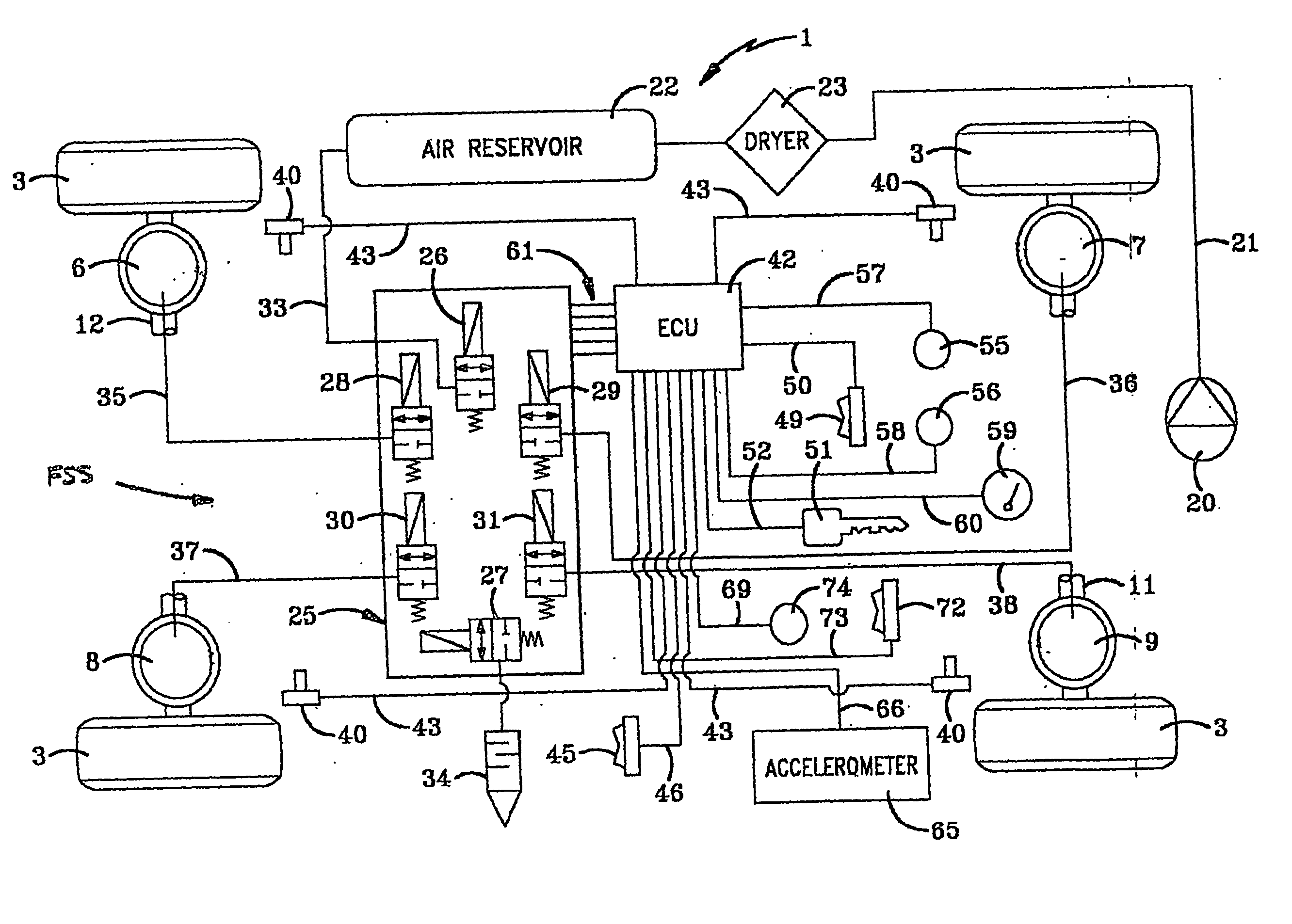
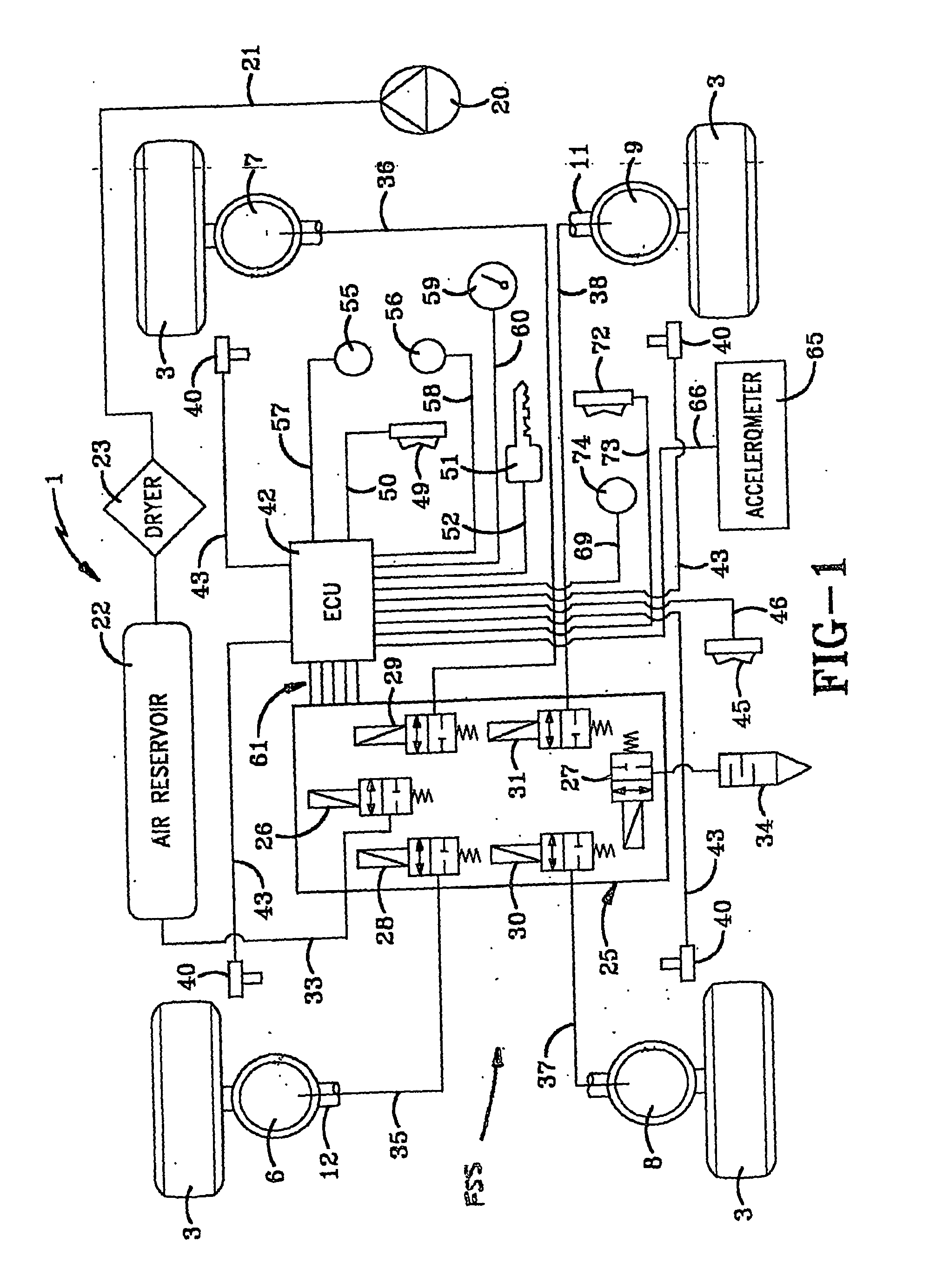
[0031]FIG. 1 is a diagrammatic representation of the horizon leveling system of the present invention which is indicated generally at 1, and illustrated as being used on an RV 2. However, system 1 can be used on other types of vehicles such as travel trailers, over-the-road truck trailers, ambulances, and personnel transport ...


PUM


Abstract

A method of positioning a vehicle chassis of a stationary vehicle in approximate alignment with a predetermined datum is provided. The vehicle has an axle and a fluid suspension system. The fluid suspension system includes a control device, a pressurized fluid source and an exhaust passage. The pressurized fluid source and the exhaust passage are in fluid communication with the plurality of fluid suspension members through the control device. The vehicle also includes an electronic control unit operatively associated with the control device. The method including steps of providing an alignment sensor supported on the chassis for outputting a signal indicative of the orientation of the chassis to the electronic control unit and acquiring a signal output by the alignment sensor. Another step includes comparing the signal from the alignment sensor to alignment data stored in the electronic control unit. A further step includes selectively operating the control device to permit fluid communication between one or more of the fluid suspension members and one of the pressurized fluid source and the fluid exhaust until the signal from the alignment sensor approximately corresponds to the alignment data. A system for performing the method is also discussed.

Description

[0001] This application claims priority from U.S. Provisional Patent Application No. 60 / 463,487 filed on Apr. 17, 2003, which is hereby incorporated herein by reference in its entirety.BACKGROUND [0002] The present invention broadly relates to air suspension systems and, more particularly, an electronically controlled air suspension system for use in association with a stationary vehicle that adjusts the air springs of the stationary vehicle to place the vehicle chassis thereof in substantial alignment with an artificial horizon or other predetermined datum. [0003] The present invention finds particular application in association with the use of larger mobile vehicles, such as recreational vehicles (RVs), travel trailers and over-the-road truck trailers, for example, and will be described herein with particular reference thereto. However, it is to be understood that such vehicles are simply exemplary structures and that the present invention is capable of broader application in asso...

Claims


Application Information

Patent Timeline
Patent Type & Authority Applications(United States)
IPC IPC(8): B60GB60G17/005B60G17/015B60G17/017B60G17/019B60G23/00
CPCB60G17/0155B60G2800/912B60G17/01908B60G2400/051B60G2400/10B60G2400/204B60G2400/252B60G2500/201B60G2500/204B60G2500/30B60G2500/32B60G2600/04B60G2600/20B60G2800/019B60G2800/20B60G17/017
Inventor BROOKES, GRAHAM R.NORDMEYER, DANIEL L.HOAGLAN, BRIAN S.HOLBROOK, GREG A.
Owner DRIVERIGHT HLDG
Why Eureka
Try Eureka