Magnetic levitation actuator

a technology of magneto-levitation actuator and actuator, which is applied in the direction of magnets, magnet bodies, switch power arrangements, etc., can solve the problems of actuators posing significant problems, the displacement of objects remains limited with respect to the size of objects, and the switching time of multi-plexers is relatively slow

Inactive Publication Date: 2005-10-27
COMMISSARIAT A LENERGIE ATOMIQUE ET AUX ENERGIES ALTERNATIVES +2
View PDF10 Cites 7 Cited by
  • Summary
  • Abstract
  • Description
  • Claims
  • Application Information

AI Technical Summary

Benefits of technology

[0027] It is possible to provide means for controlling the current to be caused to flow in the conductor, by the position of the mobile m

Problems solved by technology

This multiplexer has a relatively slow switching time.
Moreover, such actuators pose a significant problem as regards their electric power supply.
So they need to be associated with a specific power supply which poses problem in standalone applications.
Another drawback is that the displacements remain limited with respect to the size of the object.
Although the manufacturing technique is more complicated, there exist a few magnetic actuators as well.
This mechanical connection is tricky to make with collective manufacturing techniques.
Moreover,

Method used


Image

  • Magnetic levitation actuator
  • Magnetic levitation actuator
  • Magnetic levitation actuator

Examples


Embodiment Construction

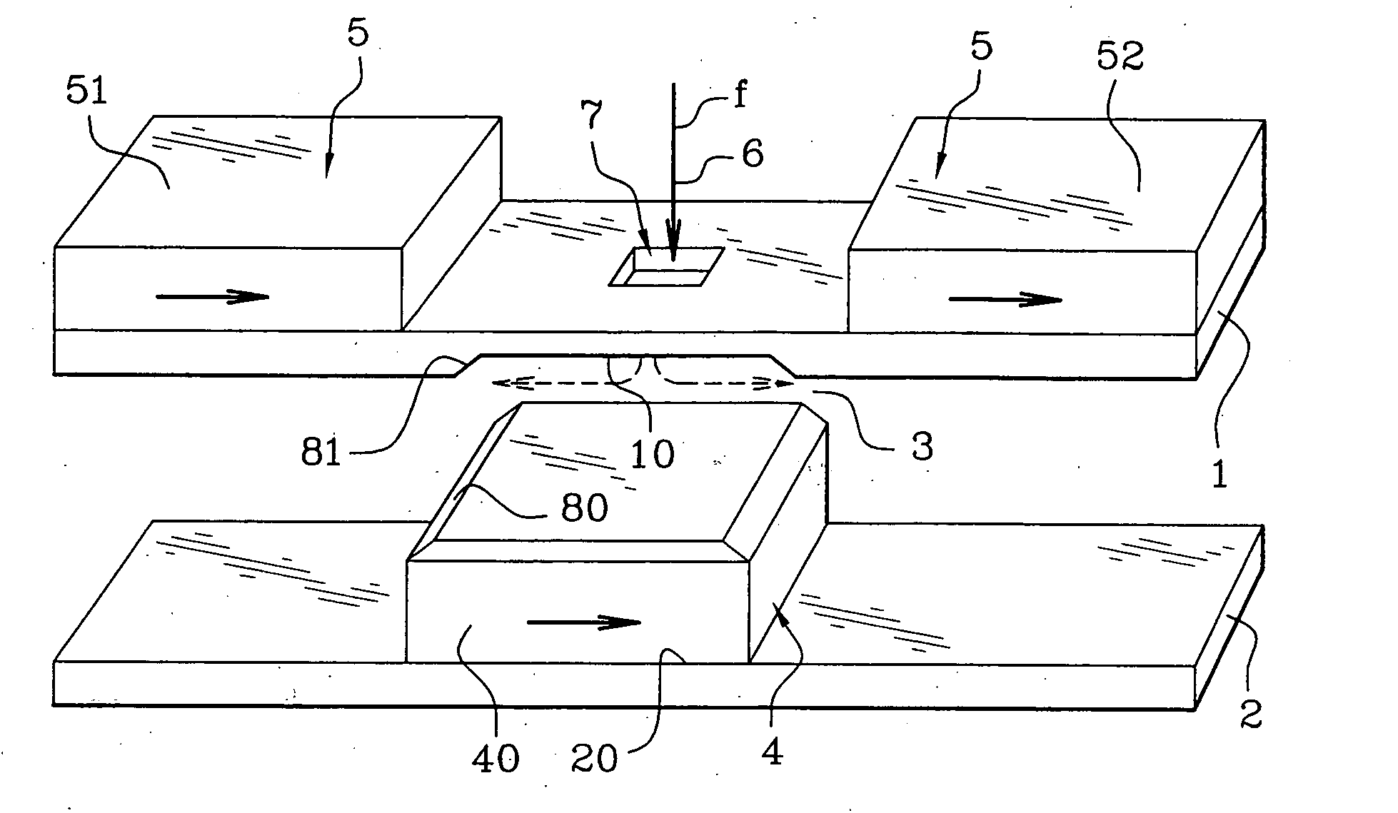
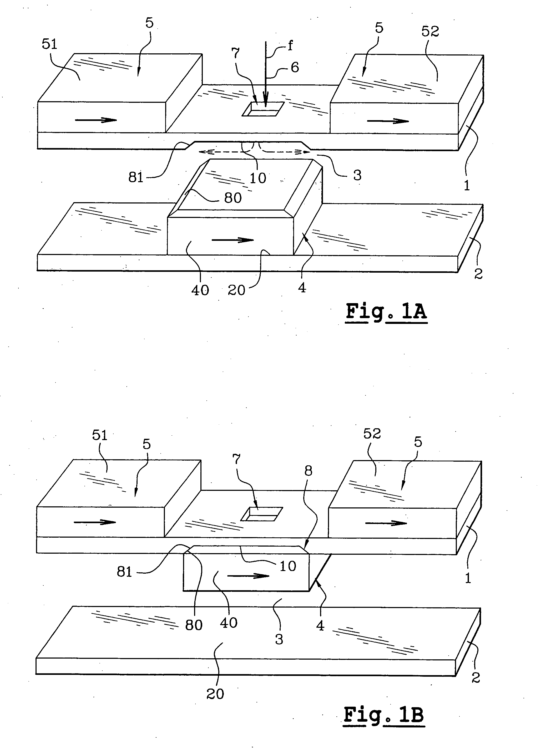
[0074] Reference will be made to FIGS. 1A, 1B which schematically show an exemplary magnetic actuator according to the invention in two different stable abutted positions. It is assumed that the actuator is a valve in this embodiment. This actuator includes a first amagnetic support 1 and a second amagnetic support 2, arranged as strata in different planes and delimiting between them a gap 3 wherein a mobile magnetic part 4 is able to move. It may be noted that there is no notion of verticality or horizontality as the mass of the actuator is very low relatively to the magnetic forces at work.

[0075] In FIGS. 1A, 1B, the supports are illustrated as plates arranged substantially in parallel, one above the other, the first support 1 being on the top and the second support 2 at the bottom. Another orientation and / or another shape of the supports are possible. Supports 1, 2 may for example, be made on the basis of a semiconducting material, such as silicon or gallium arsenide, a dielectr...


PUM


Abstract

A magnetic actuator including a mobile magnetic part, a fixed magnetic part, and a mechanism for triggering displacement of the mobile magnetic part relatively to the fixed magnetic part. At least two amagnetic supports, placed in different planes, delimit a gap between them, the fixed magnetic part being integral with at least one of the supports. The supports each have an abutment area for the mobile magnetic part, the abutment area being distinct from the fixed magnetic part. The mobile magnetic part is in levitation in the gap between both supports by magnetic guiding due to the fixed magnetic part when it does not abut against the abutment area of one of the supports. The mobile magnetic part can assume plural stable magnetic positions; in each of these positions, it abuts against a support.

Description

TECHNICAL FIELD [0001] The object of the present invention is a magnetic actuator and notably a magnetic micro-actuator which may be made by means of microtechnological techniques, i.e., micro-machining techniques used in microelectronics. [0002] Such an actuator may be used in various systems, for example as an electrical micro-relay for controlling the opening, the closing, or switching of an electrical contact, for example for controlling transistors, as an optical micro-relay for controlling the passage, the blanking out, the switching or branching of a light ray, as a microvalve or microgate for controlling the passage, the stopping or the branching of a fluid, as an impact or displacement sensor, as a micropump, as a positioner for magnetic or optical heads, for carrying out AFM (Atomic Force Microscope) or thermal recordings, in positioning tables. STATE OF THE PRIOR ART [0003] Presently, actuators made by using microtechnological techniques, are essentially thermal or electr...

Claims


Application Information

Patent Timeline
IPC IPC(8): H01F7/122H01F7/124H01F7/16H01H3/24H01H37/58H01H50/00H01H51/22H01H67/22
CPCH01F7/122H01F7/124H01F7/1646H01H3/24H01H2037/008H01H50/005H01H51/22H01H67/22H01H37/58
Inventor ROSTAING, HERVEDELAMARE, JEROMECUGAT, ORPHEELOCATELLI, CHRISTEL
Owner COMMISSARIAT A LENERGIE ATOMIQUE ET AUX ENERGIES ALTERNATIVES
Why Eureka
Try Eureka