Identification device for multilayer tubular structures

a tubular structure and identification device technology, applied in the field of smart packaging systems and methods, can solve the problems of limited read-only system, incompatibility of 1d and 2d bar code systems, and limited distance at which strip can be read, so as to achieve the effect of less likely to be seen and possibly removed

Active Publication Date: 2005-10-27
SONOCO DEV INC
View PDF11 Cites 26 Cited by
  • Summary
  • Abstract
  • Description
  • Claims
  • Application Information

AI Technical Summary

Benefits of technology

[0008] These and other needs are provided by the multilayer tubular structure and methods of forming the multilayer tubular structure according to the present invention. Advantageously, the multilayer tubular structure of the present invention includes a tubular body having an electronic detection device, such as a radio frequency identification device or tag, which is embedded therein. As such, the detection device of the present invention cannot be damaged or broken during processing or use of the multilayer tubular structure. Because the device is hidden inside the multilayer tubular body, the device is less likely to be seen and possibly removed, which is useful from a security standpoint.

Problems solved by technology

However, 1D and 2D bar code systems are often not compatible with one another, and the bar code must be clearly visible and readable by a scanner or the like in order to transfer the information associated with the bar code.
While this technology does not require a clear line-of-sight between the reader and the strip for proper reading of the information, the distance at which the strip can be read is limited, and the system is limited to read-only.
The magnetic strips are also prone to damage, which can be a problem for longer magnetic strips that contain more data.
In addition, the read range of a Bistatix tag is dependent on size, so for long read ranges a very large tag may be required.
One of the challenges that exist with electronic detection devices, and with RFID systems in particular, is how to apply a RFID tag to an item.
Currently tags are glued to an outer surface of a container or pallet, and while this method is satisfactory for many applications, the prominent location of the tag often leaves the tag exposed and subject to damage or inadvertent removal during processing.
The difficulties in applying a detection device is particularly pronounced when applying such devices or tags to tubular rolls or containers, such as those used in supporting roll goods or for packaging food products, as these types of structures often rub against one another during production and thereby cause damage to the tags.
In addition, reusable carriers or containers are often used for many cycles, such as in doffing and creeling textile yarn, which can further accelerate damage to the RFID tag.

Method used


Image

  • Identification device for multilayer tubular structures
  • Identification device for multilayer tubular structures
  • Identification device for multilayer tubular structures

Examples


Embodiment Construction

[0025] The present inventions now will be described more fully hereinafter with reference to the accompanying drawings, in which some, but not all embodiments of the invention are shown. Indeed, these inventions may be embodied in many different forms and should not be construed as limited to the embodiments set forth herein; rather, these embodiments are provided so that this disclosure will satisfy applicable legal requirements. Like numbers refer to like elements throughout.

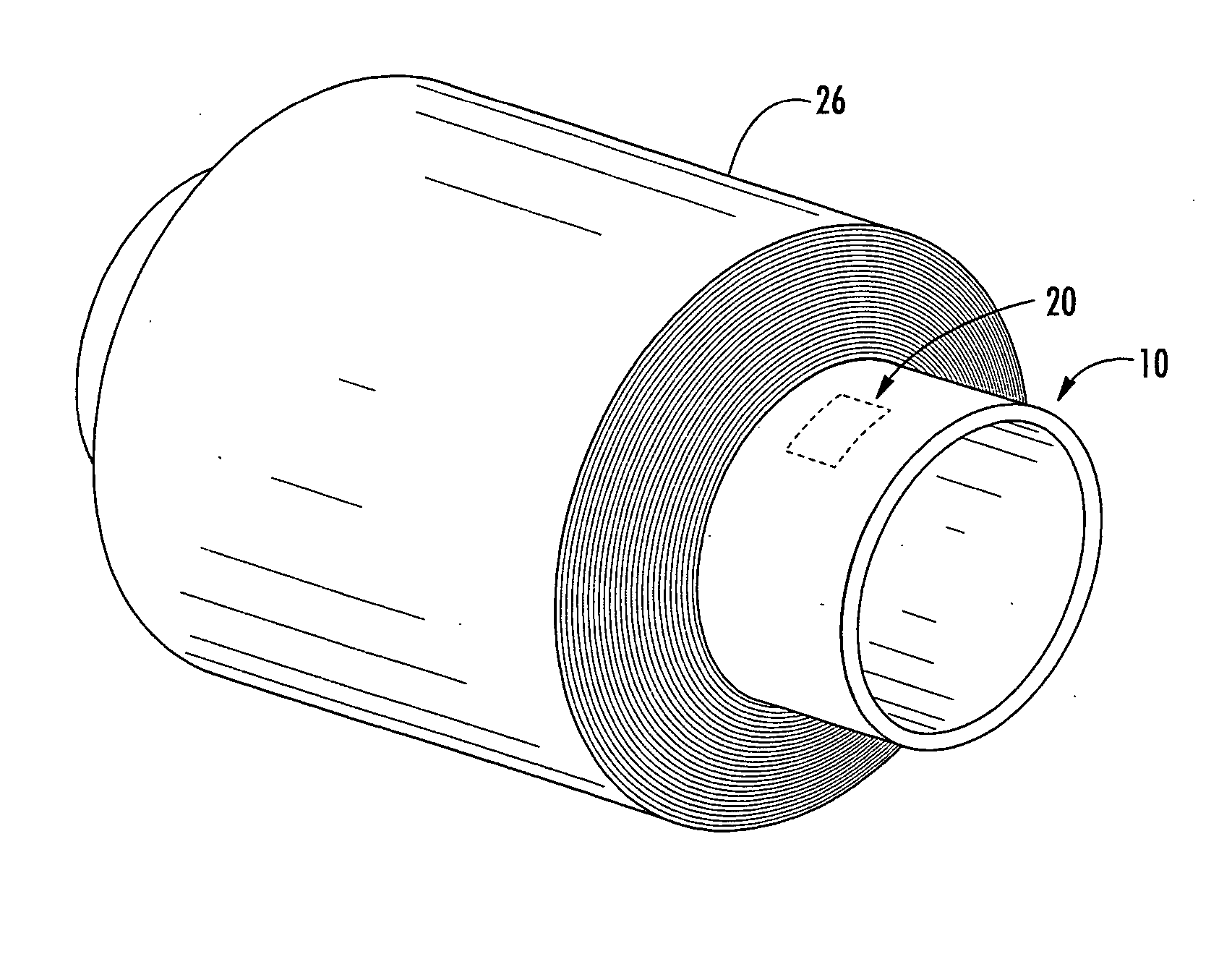
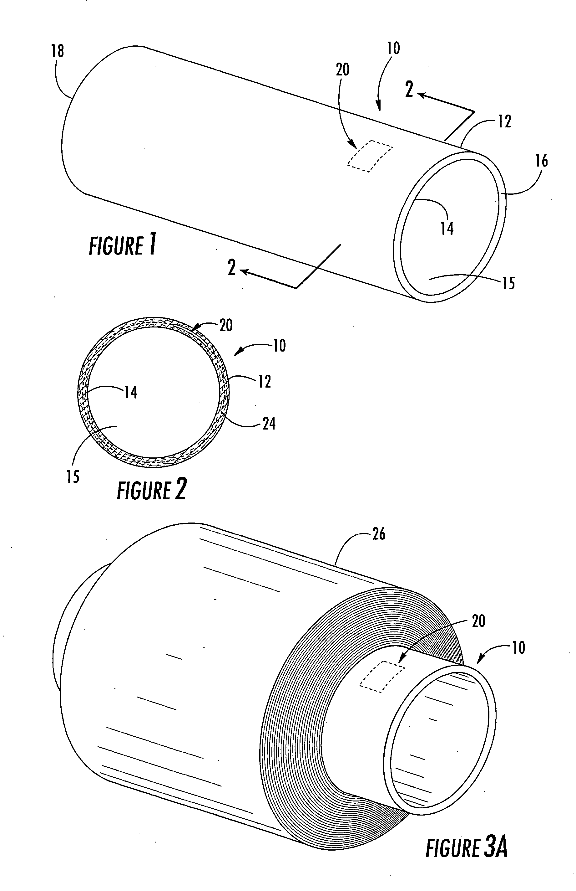
[0026] Turning to the figures, FIGS. 1 and 2 illustrate a multilayer tubular structure according to the present invention. In particular, reference number 10 refers to a multilayer tubular structure used for packaging products and the like, or to a winding core or tube such as is used to support roll goods, such as textiles, paper, plastic, and other materials.

[0027] The multilayer tubular structure 10 includes multiple layers or plies of one or more known flexible materials that are strong and particularly ...


PUM


Abstract

A multilayer tubular structure for products with an identification device being embedded or interposed between two of the multiple layers of the tubular structure. The identification device is responsive to radio frequencies and is able to store and transmit information about the multilayer tubular structure, the products, and processes that have been performed on same. A method is provided for manufacturing a multilayer tubular structure by embedding a radio frequency identification device between two of the multiple layers.

Description

BACKGROUND OF THE INVENTION [0001] The present invention relates to “smart packaging” systems and methods, and more particularly to electronic detection devices, such as radio frequency identification devices (“RFID” tags or devices hereinafter) and methods of using these devices in packaging and package tracking systems. [0002] Monitoring the location and status of items is advantageous in many applications. For example, in manufacturing environments it is important to know the whereabouts of items in a factory, and in transportation environments it is important to identify and document the coming and going of items from a warehouse or the like. Bar codes have traditionally been used to identify and track items. In particular, 1D bar codes are most common and are used to identify items at the grocery store, etc. More recently, 2D bar codes have been developed and provide substantially more information than 1D bar codes. Thus, 2D bar codes are used with shipping labels and other ite...

Claims


Application Information

Patent Timeline
Patent Type & Authority Applications(United States)
IPC IPC(8): B31C3/00B65D3/22B65D85/672
CPCB31C3/00B65D3/22B65D2211/00B65D2203/10B65D85/672B65H75/10G06K19/0723
Inventor BELLUM, CLIFFLOWRY, JAMES
Owner SONOCO DEV INC
Why Eureka
Try Eureka