Self light emitting type display module, electronic appliance loaded with the same module and verification method of faults in the same module

a display module and self-lighting technology, applied in the field of self-lighting display modules, can solve problems such as errors in numeral reading, display numerals that cannot be recognized as “0” or “8”, and pixels generated on the display panel

Inactive Publication Date: 2005-10-27
TOHOKU PIONEER CORP
View PDF4 Cites 17 Cited by
  • Summary
  • Abstract
  • Description
  • Claims
  • Application Information

AI Technical Summary

Benefits of technology

[0010] An object of the present invention is to provide a self light emitting type display module capable of detecting a fault of a self light emitting element generated during the operation of a display, verifying a situation in which the element reaches a state having a high possibility that a light emission fault may occur and notifying user thereof appropriately depending on that situation and a verifying method for a fault in the same module.

Problems solved by technology

In an injection appliance, for example, if brightness leak phenomenon occurs in the scanning line direction in a numeral display portion indicating an amount of injection, such a problem that a displayed numeral cannot be recognized to be “0” or “8” can occur.
Further, a pixel at a portion displaying a decimal point is not lit so that a numeric digit is displayed erroneously and as a consequence, there may occurs a problem that the numeral may be read out mistakenly without this point being noticed.
User's continuous use of the aforementioned machine mistakenly recognized that the display in such a fault condition is in normal condition is extremely dangerous and needless to say, this may lead to a fatal problem.
Although if the evaluation device disclosed in the Japanese Patent No. 3437152 is used, such an effect that an initial fault of a product can be found out and an appropriate measure can be taken before the display panel having the fault is delivered to user can be enjoyed, this kind of the display has a problem that a new fault can be generated in pixels disposed on the display panel during an operation of the display unit after the product is shipped.
However, to solve the fault in the pixel generated during the operation of the display and a problem that a fault may occur in the aforementioned drive means or the like, there exist extremely many technical problems and it is almost difficult to provide a display module in which no aforementioned fault occurs after the product is shipped.
However, the inventor of this application has reached a finding that by verifying the impedance characteristic of the element when the reverse bias is applied precisely, a state having a high possibility that a lighting fault may occur in the future can be detected (there exists a latent fault factor).

Method used


Image

  • Self light emitting type display module, electronic appliance loaded with the same module and verification method of faults in the same module
  • Self light emitting type display module, electronic appliance loaded with the same module and verification method of faults in the same module
  • Self light emitting type display module, electronic appliance loaded with the same module and verification method of faults in the same module

Examples


Embodiment Construction

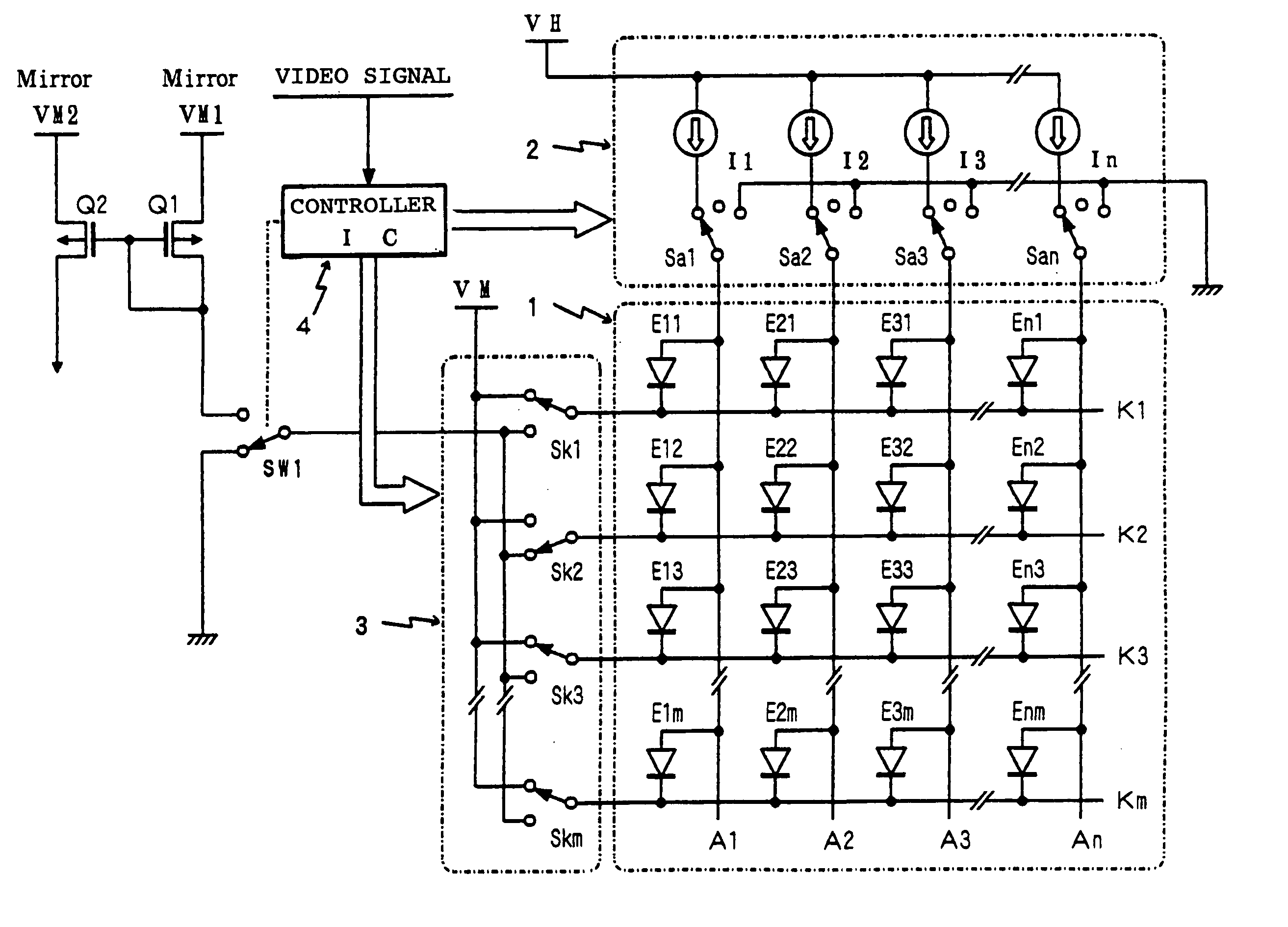
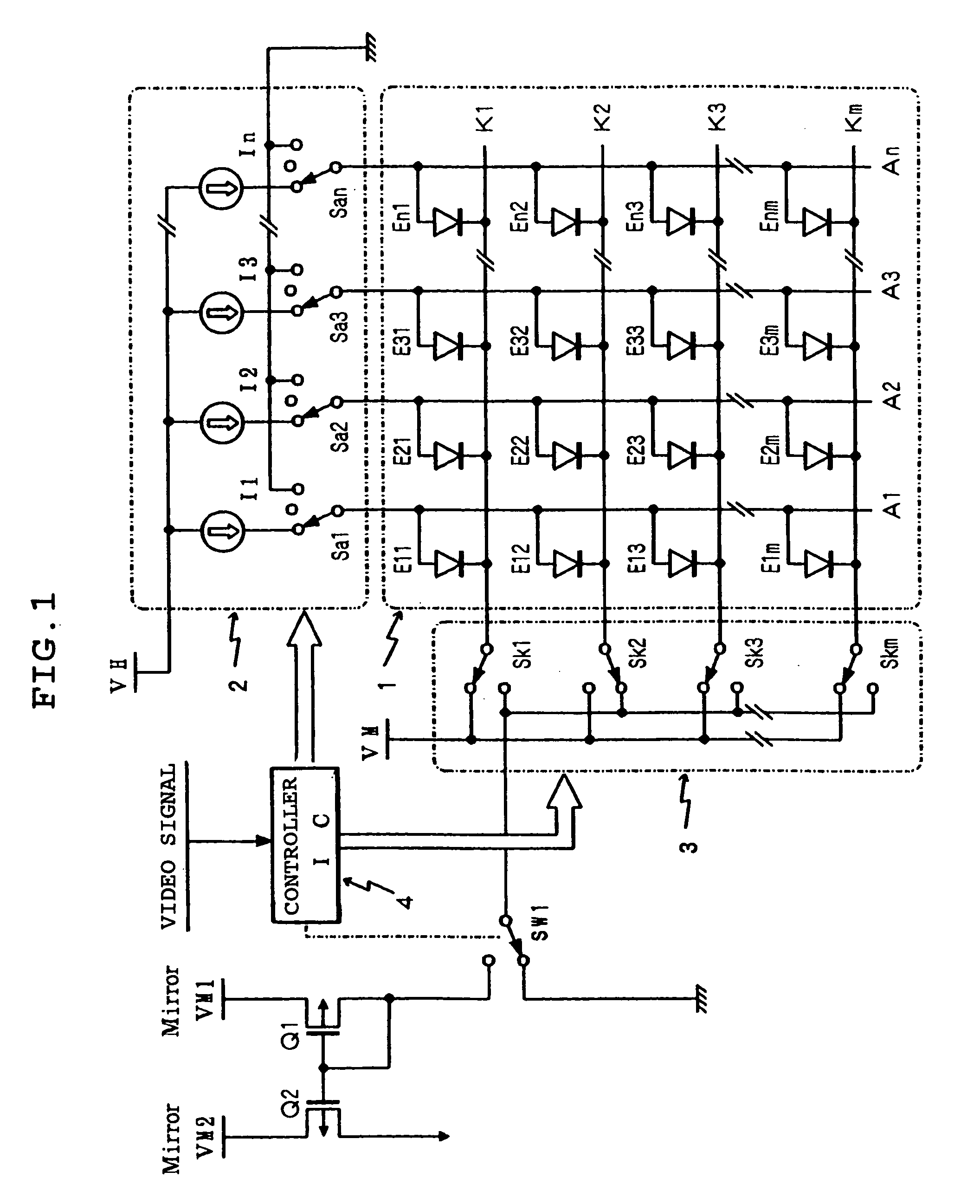
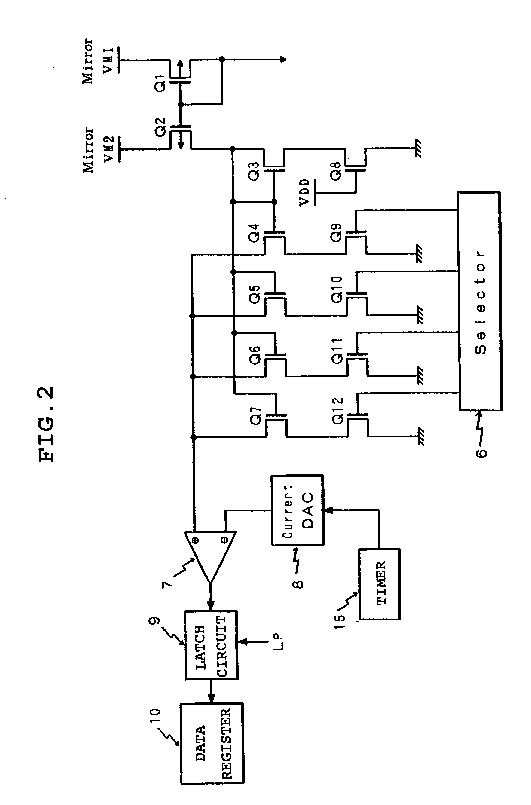
[0019] Hereinafter, the self light emitting display module of the present invention will be described as regards the embodiments shown in Figures. The self light emitting display module of the present invention comprises a light emitting display panel in which a plurality of self light emitting elements as pixels is arranged in a matrix configuration, a self light display unit comprised of drive means for driving to light each self light emitting element on this light emitting display panel selectively, fault detecting means for detecting a fault in the self light emitting display unit and memory means for storing this detection result. As an embodiment described below, an example in which an organic EL element employing organic material for its light emitting layer is adopted will be indicated.

[0020] The organic EL element is basically formed by laminating a transparent electrode, for example, constituting an anode on a transparent substrate of glass or the like, a light emitting ...


PUM


Abstract

Reverse bias voltage VM is applied to any one of self light emitting elements arranged on a light emitting panel 1 under detection mode. Current corresponding to weak current flowing to the element is supplied to a transistor Q3 by the operation of a current mirror circuit comprised of transistors Q1, Q2. The current mirror circuit is formed with the transistor Q3 as a control side current source transistor and transistors Q4 to Q7 as a controlled side current source transistor. The sizes of the controlled side current source transistors Q4 to Q7 are set to, for example, 1:2:4:8 with respect to the control side current source transistor Q3 so as to construct current amplifying means. Current value amplified by a current comparison type comparator 7 is compared with current value from a reference current source 8 and its output is latched by a latch circuit 9 and stored in a data register 10. If a weak current over a predetermined value flows when reverse bias voltage is applied to the self light emitting element, it is determined that a possibility that the self light emitting element turns into a light emission fault is high and notifying means is driven appropriately using data stored in the data register 10.

Description

BACKGROUND OF THE INVENTION [0001] Field of the Invention [0002] The present invention relates to a light emitting display panel using an organic EL (electroluminescence) element as a self light emitting type element and a self light emitting type display module provided with drive means for driving to light this. More particularly, the present invention relates to a self light emitting type display module provided with a function capable of detecting a state in which a lighting fault is generated in mainly the self light emitting element of the light emitting display panel or a state having a high possibility that the lighting fault may occur in the future and a verification method for the fault in the same module. DESCRIPTION OF THE RELATED ART [0003] A number of electronic appliances and the like provided currently include a display and the display is indispensable as a man-machine interface for machines supporting the information society. The aforementioned display has been dema...

Claims


Application Information

Patent Timeline
Patent Type & Authority Applications(United States)
IPC IPC(8): H05B33/12G08B21/00G09F9/00G09G3/00G09G3/20G09G3/30G09G3/32H01L51/50H05B33/14
CPCG09G3/006G09G3/2011G09G3/3216G09G3/3233G09G2330/12G09G3/3283G09G2300/0842G09G2310/0256G09G2330/10G09G3/3266
Inventor SATO, HIROYUKISATOH, KAZUHIROGOTO, TAKASHI
Owner TOHOKU PIONEER CORP
Why Eureka
Try Eureka