Machine tool

a technology of machine tools and tools, applied in the field of machine tools, can solve the problems of increasing the size of the overall machine, and achieve the effects of compact overall machine, easy to see, and small cover

Inactive Publication Date: 2005-10-27
FANUC LTD
View PDF16 Cites 8 Cited by
  • Summary
  • Abstract
  • Description
  • Claims
  • Application Information

AI Technical Summary

Benefits of technology

[0009] According to the present invention, the display device is positioned in the observation window to thereby eliminate the need to provide a dedicated space for the display device on the cover. Accordingly, the cover can be made smaller and the overall machine can be made compact.
[0010] Further, the present invention makes it possible to arrange the display device where it can be seen easily by an operator together with the observation window, and because any image on the display device disappears during operation of the machine tool and the display device becomes transparent or semi-transparent, the state of the workpiece can be easily confirmed by looking at the machining area from the observation window.

Problems solved by technology

However, the conventional machine tool described above has a problem that the cover becomes large and thus the size of the overall machine increases because the cover is required to have a sufficient size for providing the display device and the control panel even if the machining area is not so large.

Method used


Image

  • Machine tool
  • Machine tool
  • Machine tool

Examples


first embodiment

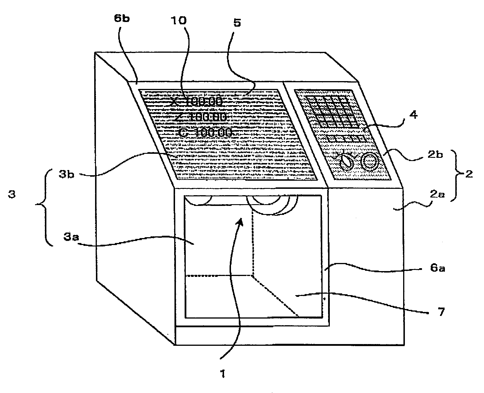
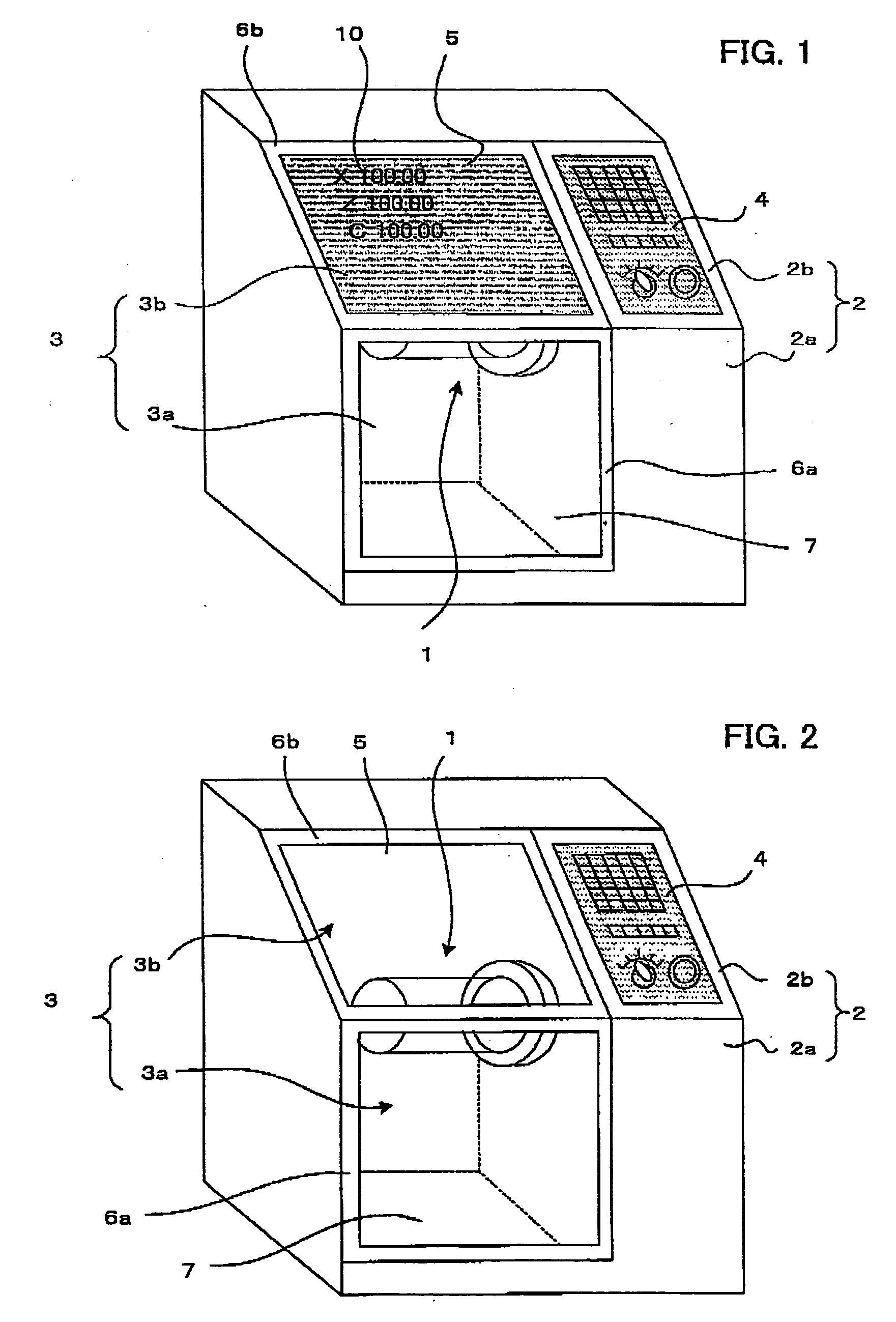
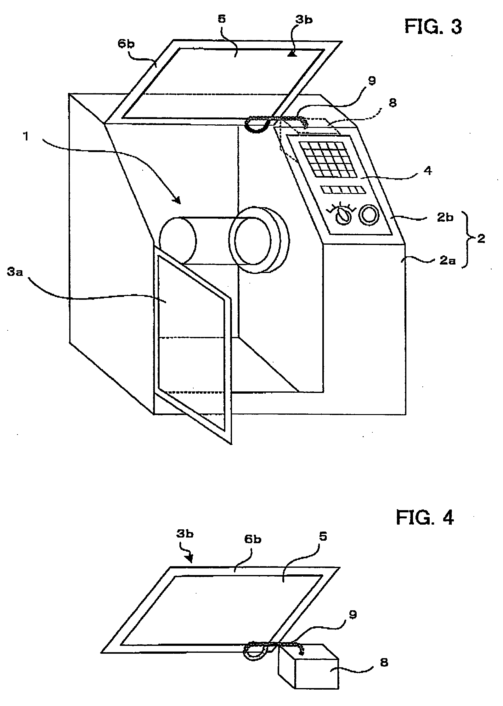
[0018] the present invention is shown in FIGS. 1-4. As shown in FIGS. 1-3, the machine tool of the present invention comprises a cover 2 which encloses the entire machine tool including a machining area space 1, and an observation window 3 and a control panel 4 is provided on a front surface of the cover 2. Further, a display device 5 is provided on the observation window 3.

[0019] The machining area space 1 is an area where a workpiece is machined by a tool, and since cutting waste and cutting fluid scatter from a machining point the machining area space 1 is enclosed by the cover 2. Then, in order to monitor a machining state, the observation window 3 with a cover made of a transparent material is provided in the cover 2 enclosing the machining area space 1.

[0020] The cover 2 encloses at least the machining area space 1 of the machine tool, and is made of an opaque and durable material such as metal except for the observation window 3.

[0021] In this embodiment, a front bottom por...

second embodiment

[0029] the present invention is shown in FIGS. 5 and 6. FIG. 5 is a front view of the machine tool when the display device is in use and FIG. 6 is a front view of the machine tool when the display device is not in use.

[0030] An observation window 3 which is hinged to be opened and closed is provided at an upper portion of a front surface of the cover 2 which encloses the machining area space 1 of the machine tool. The control panel 4 is arranged below the observation window 3 on the front surface of the cover 2.

[0031] The display device 7 for displaying an image 10 is provided at a part of the transparent panel 7 of the observation window 3, as shown in FIG. 5. The display device 5 becomes transparent or semi-transparent when the image 10 disappears, as shown in FIG. 6, so that the machine tool machining area space 1 is visible. It should be noted that the remaining structures are substantially identical to those of the first embodiment.


PUM


Abstract

A machine tool having a transparent observation window on a front surface of a cover that encloses a machining area space, and a display device provided in the observation window that becomes transparent or semi-transparent when a displayed image disappears. A control panel may be arranged below the observation window.

Description

BACKGROUND OF THE INVENTION [0001] 1. Field of the Invention [0002] The present invention relates to a machine tool, and more particularly to a machine tool with a cover enclosing a machining area space to prevent scattering of cutting waste and cutting fluid. [0003] 2. Description of Related Art [0004] There is known a machine tool with a cover enclosing a machining area space, which is called a splash guard, so as to prevent cutting waste and cutting fluid from scattering and thus dirtying the surroundings. In a machine tool of this type, a transparent observation window is provided in a front of the cover in order to check condition of a workpiece. In addition, a display device for displaying a machining program and setting data, a keyboard for inputting data and a control panel provided with various operating switches are arranged on a front surface of the machine tool. See, for example, Seiken YAMAGISHI, “Zukai NC Kousaku Kikai no Nyuumon” (Illustrated Introduction to NC Machin...

Claims


Application Information

Patent Timeline
Patent Type & Authority Applications(United States)
IPC IPC(8): B23Q1/00B23Q11/08G09G3/36
CPCB23Q11/08B23Q11/0891
Inventor KANDA, KUNIOYAMATO, SHINOBU
Owner FANUC LTD
Why Eureka
Try Eureka