Microchip and fluorescent particle counter with microchip

a technology of fluorescent particle counter and microchip, which is applied in the field of microchips, can solve the problem of a rather long time for the proportion, and achieve the effect of reducing the number of repetitions and improving the accuracy of counting

Inactive Publication Date: 2005-10-27
KOWA CO LTD
View PDF7 Cites 17 Cited by
  • Summary
  • Abstract
  • Description
  • Claims
  • Application Information

AI Technical Summary

Benefits of technology

[0043] In this case, repeat counting is reduced so as to improve the accuracy of counting.

Problems solved by technology

Besides, passage of the mixing portion takes a rather longer time, thereby sufficiently reacting the first and second liquid during the passage.

Method used


Image

  • Microchip and fluorescent particle counter with microchip
  • Microchip and fluorescent particle counter with microchip
  • Microchip and fluorescent particle counter with microchip

Examples


Embodiment Construction

[0051] Best modes of embodiment for executing the invention are now explained, referring to FIG. 1 through FIG. 3 and FIGS. 6 and 7.

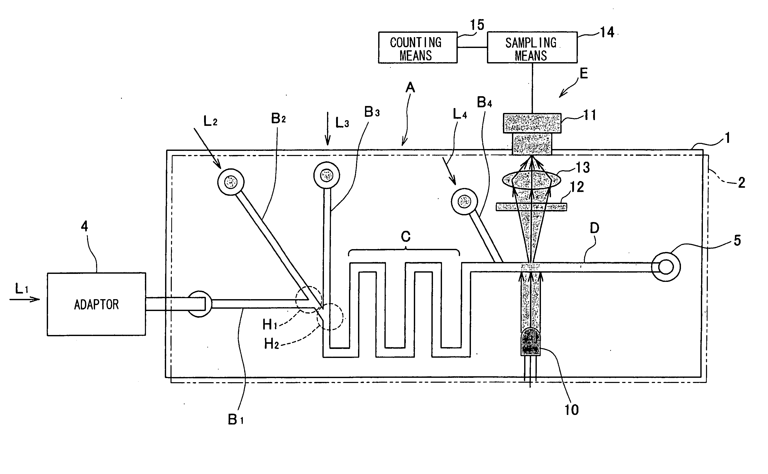
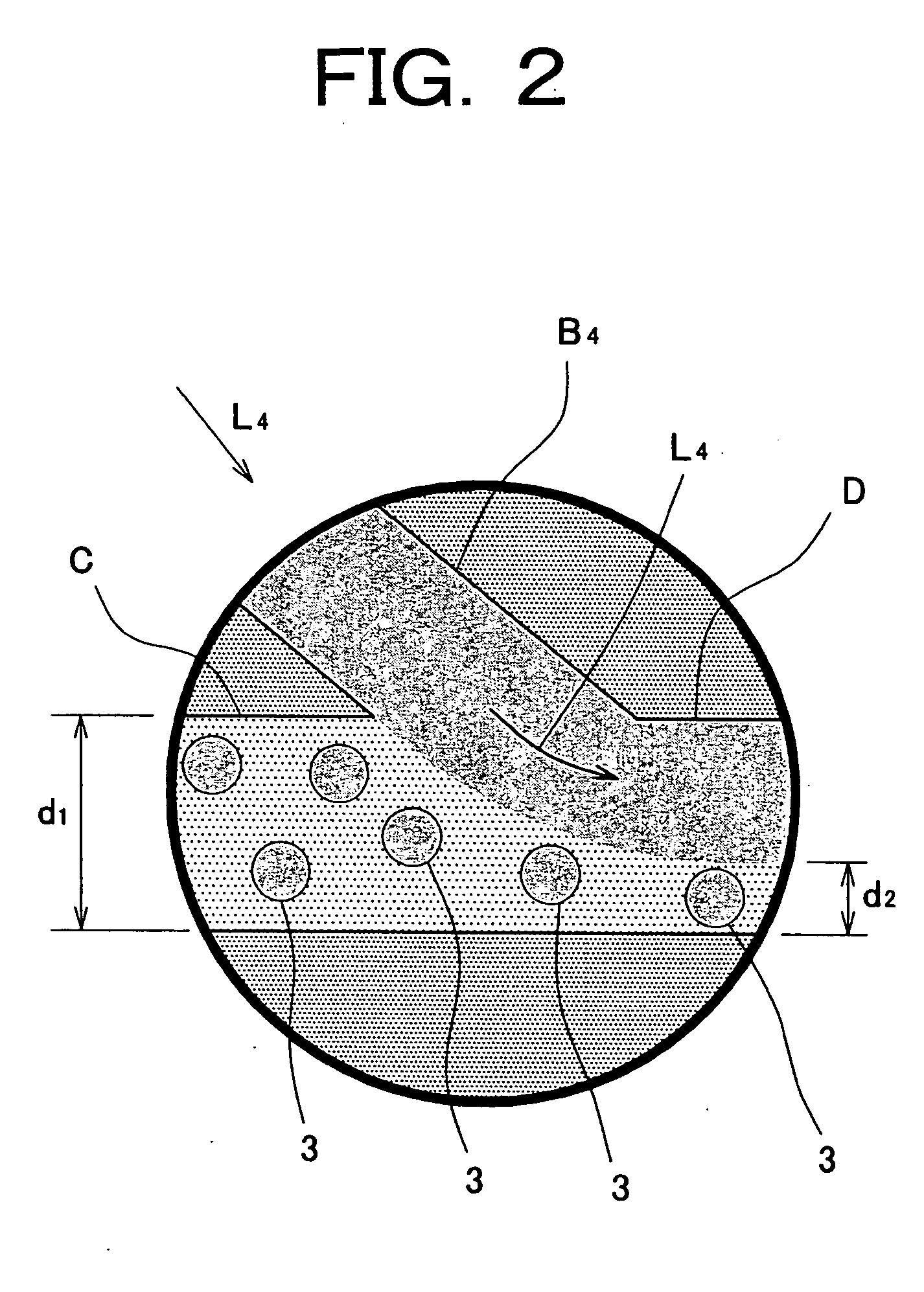
[0052]FIG. 1 is a typical view showing structures of a microchip and a fluorescent particle counter according to the invention, FIG. 2 is a typical view showing a way of aligning fluorescent particles through an inflow of fourth liquid, FIG. 3(a) is a typical view for explaining a method of counting fluorescent particles, and FIG. 3(b) is a view showing a wave form of a fluorescent intensity distribution along a gate 20 of FIG. 3(a). And, FIG. 6 is a typical view for explaining another method of counting fluorescent particles, and FIG. 7 is a typical view for explaining further another method of counting fluorescent particles.

[0053] A microchip according to the invention depicted as A in FIG. 1 has a first inflow passage B1 into which first liquid L1 flows, a second inflow passage B2 into which second liquid L2 flows, a mixing portion C connecting wit...


PUM

PropertyMeasurementUnit
fluorescentaaaaaaaaaa
fluorescent particle countingaaaaaaaaaa
fluorescenceaaaaaaaaaa

Abstract

When connecting a blood collecting unit (not shown) with an adaptor, streaming blood in a first inflow passage, and streaming liquid including surfactant or fluorescent dyes in a second inflow passage, the blood and the liquid are mixed at a mixing portion, and platelets, erythrocytes and cell membranes of leukocytes in the blood are dissolved by the surfactant, and the nuclei of the leukocytes are fluorescently stained with the fluorescent dyes. Then, a fluorescent particle counting portion counts the fluorescently stained nuclei of the leukocytes during moving in an outflow passage. According to the invention, a number of leukocytes can be correctly measured with a simple operation, such as connection of a blood collecting unit or the like with the adaptor.

Description

BACKGROUND OF THE INVENTION [0001] This invention relates to a microchip for mixing two or more liquid, and a fluorescent particle counter with the microchip. [0002] In various technical fields, number of particles has been counted after fluorescently staining. In a medical field, for instance, platelet products and erythrocyte products which are made by respectively extracting platelets and erythrocytes from blood are used. It is preferable that no leukocyte remains in platelet products and erythrocyte products. For this reason, leukocytes are removed in a process of producing. In order to confirm whether or not leukocytes have been removed from a platelet product or an erythrocyte product, number of leukocytes is counted (see a Japanese patent application (Publication No. 2001-83092, for instance). [0003]FIG. 4 is a block diagram showing a structure of a conventional leukocyte counter. A reference number 100 of FIG. 4 denotes a container for containing fluorescently stained platel...

Claims


Application Information

Patent Timeline
Patent Type & Authority Applications(United States)
IPC IPC(8): B01L3/00G01N1/38G01N15/14G01N21/00G01N21/64
CPCB01F5/0646B01F5/0647B01F13/0059B01L3/502776G01N2015/1486B01L2300/0867G01N15/1468G01N21/6428B01L2200/10B01F25/4331B01F25/433B01F33/30
Inventor HIRONO, TAISUKE
Owner KOWA CO LTD
Why Eureka
Try Eureka