Lens module and assembling method thereof

a technology of lens module and assembling method, which is applied in the field of lens module and an assembling method thereof, can solve the problems of large-scale production of lens module, high cost, and generally suffer from the disadvantage of a relatively high defect rate, so as to reduce the possibility of contamination and improve the yield rate of production

Inactive Publication Date: 2005-10-27
HON HAI PRECISION IND CO LTD
View PDF8 Cites 15 Cited by
  • Summary
  • Abstract
  • Description
  • Claims
  • Application Information

AI Technical Summary

Benefits of technology

[0009] In accordance with another aspect of the present invention, an assembling method of a lens module is provided, and comprises the following steps. First, the lens module is divided into a module body and a mating receptacle electrically interconnected with the module body. The module body has a lens unit and an image sensing and processing unit. The mating receptacle has conductive terminals for transmitting an image signal produced from the image sensing and proces

Problems solved by technology

Nowadays, the mass-production of a lens module that is widely applied in an electronic device with a photograph function (such as a mobile phone with a photograph function or a personal digital assistant (PDA) with a photograph function), generally suffers from the disadvantage of a relatively high defect rate.
Howe

Method used


Image

  • Lens module and assembling method thereof
  • Lens module and assembling method thereof
  • Lens module and assembling method thereof

Examples


Embodiment Construction

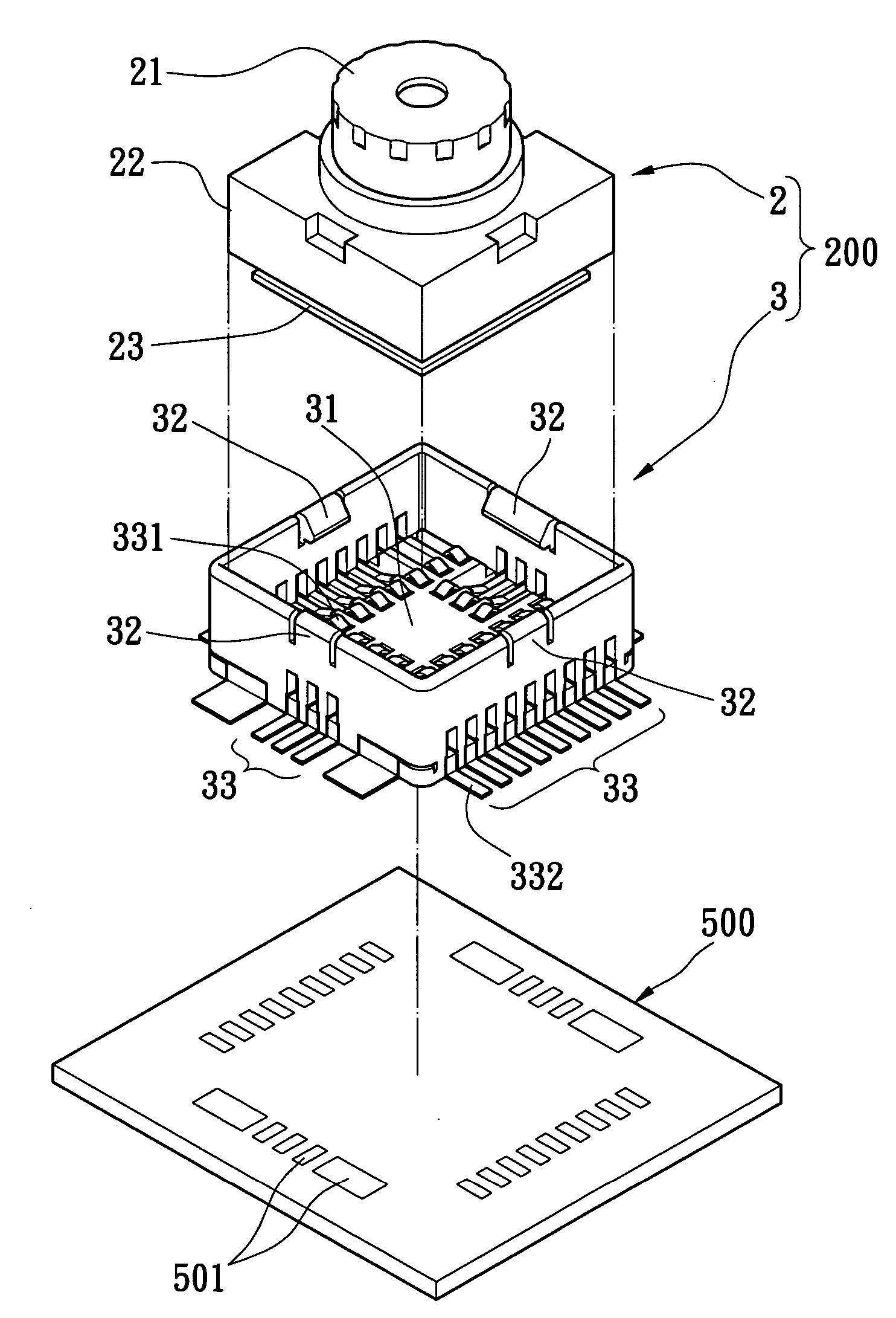
[0022] Referring to FIG. 4 to FIG. 7, a lens module 200 of the present invention includes a module body 2 and a mating receptacle 3.

[0023] The module body 2 uses a base 22 to receive a lens unit 21, an image sensing and processing unit 23 and a plurality of conductive terminals 231 (as shown in FIG. 6).

[0024] The mating receptacle 3 is made of a conventional insulating material, which has a positioning groove 31 and a plurality of conductive terminals 33. In assembly, the positioning groove 31 guides the module body 2 to be positioned quickly, thereby finishing an electrical interconnection between inner ends 331 of the terminals 33 and the terminals 231 accurately, and causing outer ends 332 of the terminals 33 to connect electrically to corresponding welds 501 of a printed circuit board 500. More preferably, fastening members 32 are defined on the mating receptacle 3 for fastening the module body 2. In other words, the mating receptacle 3 and the module body 2 are detachably eng...


PUM


Abstract

A lens module has a module body and a mating receptacle. The module body has a lens unit and an image sensing and processing unit, the image sensing and processing unit receiving light beams from the lens unit and producing an image signal. The mating receptacle is made of insulating material, which is detachably engaged with the module body and has conductive terminals formed therein for transmitting the image signal. An assembling method of the lens module includes the following steps. First, the mating receptacle is installed on a printed circuit board of an electronic device by a surface mounting technology. Second, the module body is installed in the mating receptacle to implement electrical interconnection between the module body and the printed circuit board.

Description

BACKGROUND OF THE INVENTION [0001] 1. Field of the Invention [0002] The present invention relates to a lens module and an assembling method thereof, and more particularly, to a lens module and an assembling method thereof capable of achieving an electrical interconnection with a printed circuit board of an electronic device through a mating receptacle. [0003] 2. Description of Prior Art [0004] Nowadays, the mass-production of a lens module that is widely applied in an electronic device with a photograph function (such as a mobile phone with a photograph function or a personal digital assistant (PDA) with a photograph function), generally suffers from the disadvantage of a relatively high defect rate. [0005] Referring to FIG. 1 and FIG. 2, a conventional lens module 1 comprises a lens unit 11, a base 12, an image sensor 131, a fixing substrate 14 and a flexible printed circuit board (FPCB) 13. The base 12 holds the lens unit 11 and has a top opening for introducing exterior light bea...

Claims


Application Information

Patent Timeline
IPC IPC(8): G02B6/36G02B7/02H01J40/14H01L21/58H01L21/60H01L23/22H01L23/48H01L27/00H01L27/146H01L31/0232H04N1/04H04N5/225H04N5/335H05K
CPCG02B7/02H04N5/2257H04N5/2253H04N23/54H04N23/57
Inventor LUNG, CHIEN-LIH
Owner HON HAI PRECISION IND CO LTD
Why Eureka
Try Eureka