Transmission apparatus

a technology of transmission apparatus and transmission line, which is applied in the field of transmission apparatus, can solve the problems of high-level failure recovery system and serious damage to service, and achieve the effect of improving transmission quality and reliability

Inactive Publication Date: 2005-10-27
FUJITSU LTD
View PDF24 Cites 47 Cited by
  • Summary
  • Abstract
  • Description
  • Claims
  • Application Information

AI Technical Summary

Benefits of technology

[0019] In view of the foregoing, it is an object of the present invention to provide a transmission apparatus which can circumvent a failure by establishing an efficient recovery-path at a high speed and can improve the transmission quality and the reliability.

Problems solved by technology

In an optical network where a rapidly increasing volume of communication traffic flows, a line disconnection, a node failure, or any other failure causes serious damage to service.
Accordingly, a high-level failure recovery system is desperately needed.

Method used


Image

  • Transmission apparatus
  • Transmission apparatus
  • Transmission apparatus

Examples


Embodiment Construction

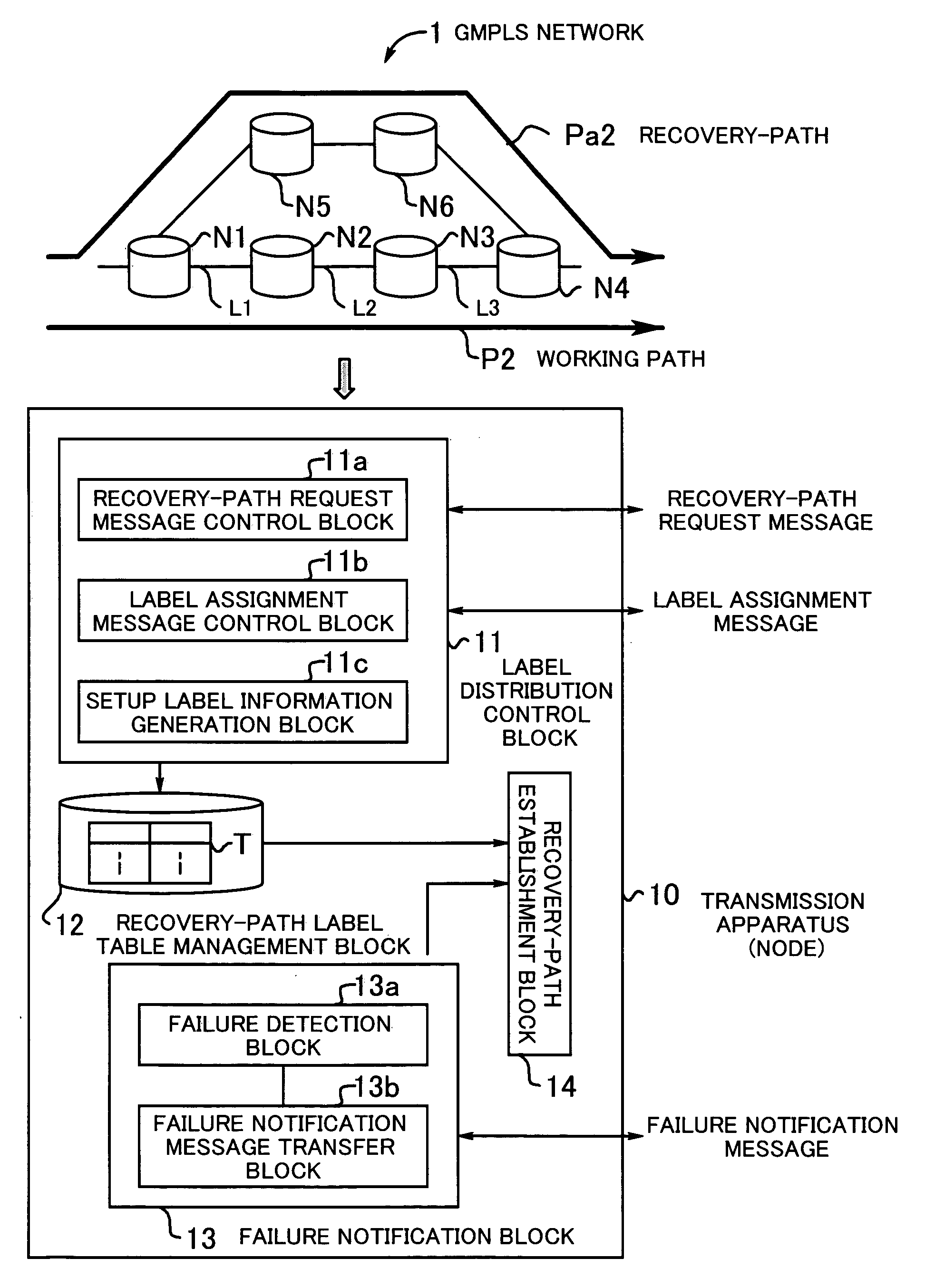
[0061] An embodiment of the present invention will be described below with reference to the drawings. FIG. 1 shows an overview of a transmission apparatus according to the present invention. A transmission apparatus (node) 10 includes a label distribution control block 11, a recovery-path label table management block 12, a failure notification block 13, and a recovery-path establishment block 14. The transmission apparatus 10 performs signal transmission based on GMPLS label switching while performing failure circumvention control. All nodes N1 to N6 included in a GMPLS network 1 have the functions of the transmission apparatus 10.

[0062] The label distribution control block 11 has a recovery-path request message control block 11a, a label assignment message control block 11b, and a setup label information generation block 11c. The label distribution control block 11 distributes a label among nodes under a label distribution protocol, such as the constraint-based routing using label...


PUM


Abstract

A transmission apparatus which can enhance the transmission quality and reliability by establishing a recovery-path efficiently at a high speed for failure circumvention. A recovery-path request message control block generates, sends, and receives a recovery-path request message containing failure location information and recovery-path setup information. A label assignment message control block generates, sends, and receives a label assignment message. A setup label information generation block generates setup label information. A recovery-path label table management block constructs and manages a recovery-path label table. A failure detection block detects the location of a failure. A failure notification message transfer block transfers a failure notification message containing failure location information. A recovery-path establishment block establishes a recovery-path by comparing failure location information contained in a failure notification message and failure location information contained in a recovery-path label table and by selecting setup label information corresponding to matching failure location information.

Description

[0001] This application is a continuing application, filed under 35 U.S.C. §111(a), of International Application PCT / JP2003 / 006035, filed May 14, 2003.BACKGROUND OF THE INVENTION [0002] 1. Field of the Invention [0003] The present invention relates to transmission apparatuses, and particularly to a transmission apparatus for performing signal transmission based on label switching while performing failure circumvention control. [0004] 2. Description of the Related Art [0005] As the use of the Internet has been spreading, the traffic of Internet Protocol (IP) packets has been increasing in these days. The variety of contents in IP packets has also been increasing. Besides traditional computer data, an increasing amount of audio data, moving images, and other data that should be processed in real time are transmitted. Label switching in layer 2, or a technology for adding a destination label to an IP packet, receives attention under circumstances where the IP-packet transmission time s...

Claims


Application Information

Patent Timeline
Patent Type & Authority Applications(United States)
CPCH04L45/00H04L45/50H04L45/28
Inventor KANO, SHINYASOUMIYA, TOSHIOCHUGO, AKIRA
Owner FUJITSU LTD
Why Eureka
Try Eureka