Method and system for charge sensing with variable gain, offset compensation, and demodulation

a charge sensing and variable gain technology, applied in the field of capacitive sensing, can solve the problem of insufficient measurement accuracy

Inactive Publication Date: 2005-10-27
AVAGO TECH INT SALES PTE LTD
View PDF18 Cites 24 Cited by
  • Summary
  • Abstract
  • Description
  • Claims
  • Application Information

AI Technical Summary

Problems solved by technology

Using conventional techniques, however, these measurements are not as accurate as needed.

Method used


Image

  • Method and system for charge sensing with variable gain, offset compensation, and demodulation
  • Method and system for charge sensing with variable gain, offset compensation, and demodulation
  • Method and system for charge sensing with variable gain, offset compensation, and demodulation

Examples


Embodiment Construction

[0016] The following detailed description of the present invention refers to the accompanying drawings that illustrate exemplary embodiments consistent with this invention. Other embodiments are possible, and modifications may be made to the embodiments within the spirit and scope of the invention. Therefore, the detailed description is not meant to limit the invention. Rather, the scope of the invention is defined by the appended claims.

[0017] It would be apparent to one of skill in the art that the present invention, as described below, may be implemented in many different embodiments of software, hardware, firmware, and / or the entities illustrated in the figures. Any actual software code with the specialized control of hardware to implement the present invention is not limiting of the present invention. Thus, the operational behavior of the present invention will be described with the understanding that modifications and variations of the embodiments are possible, given the leve...


PUM


Abstract

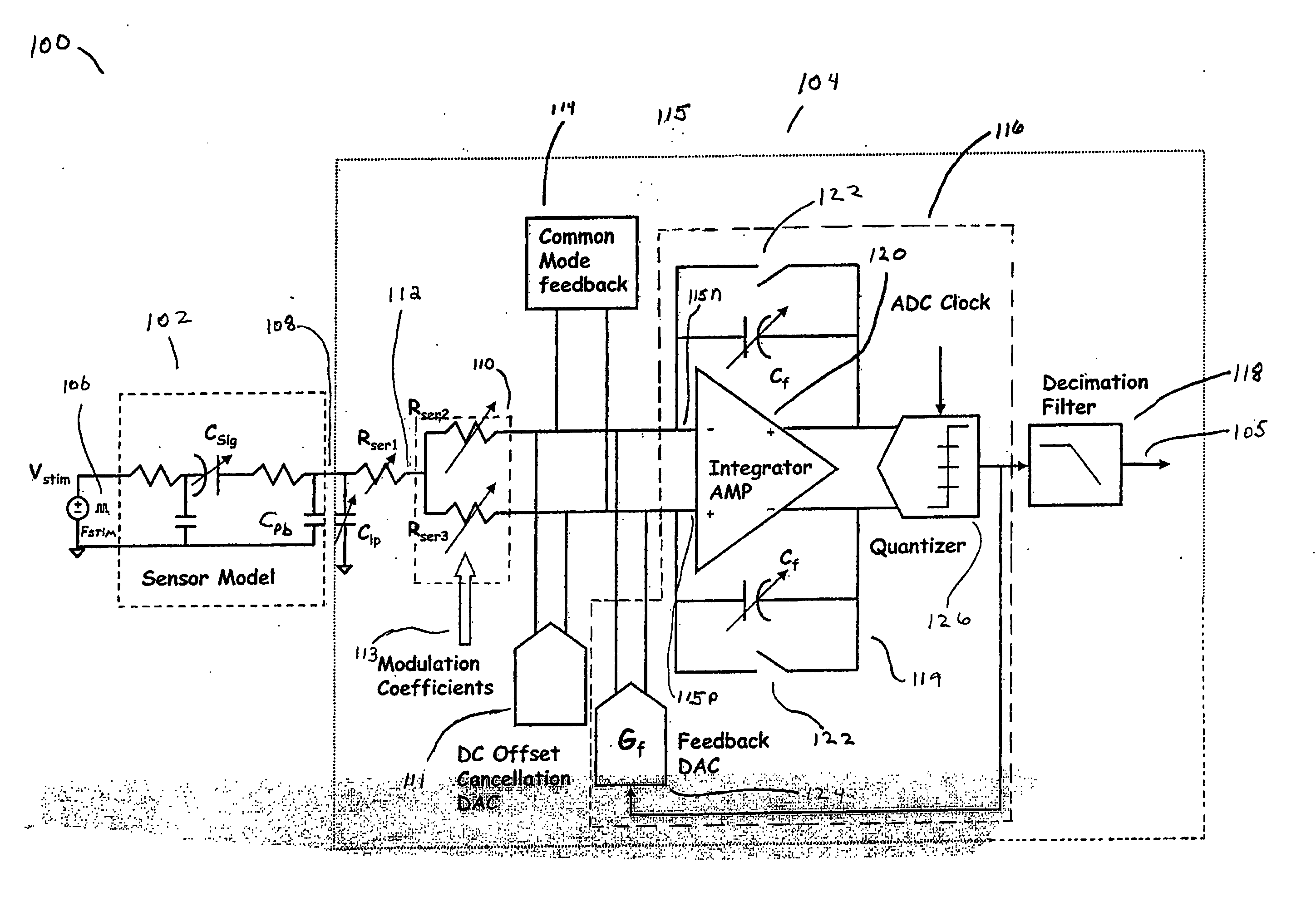
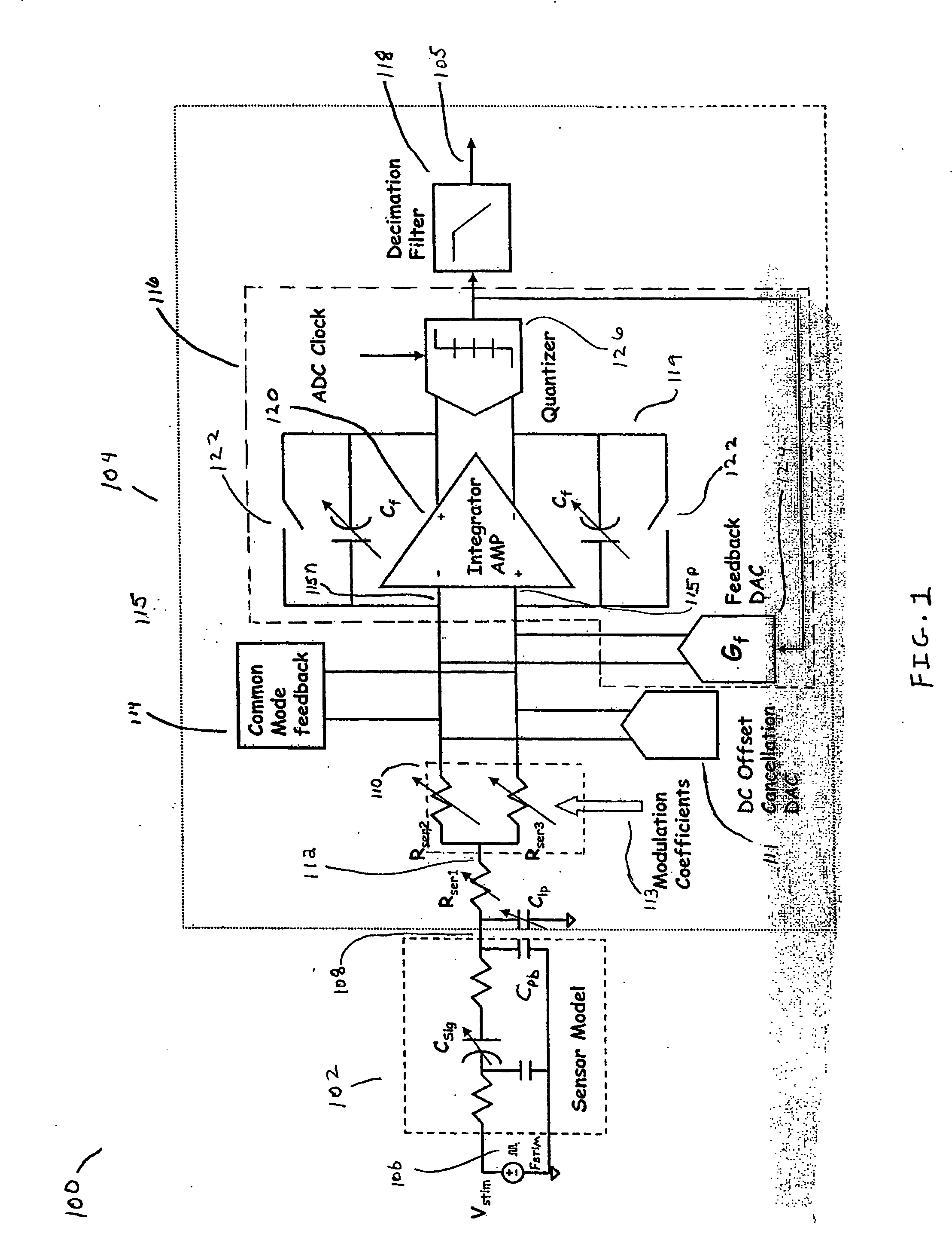
Provided are a method and system for digitizing a sensor model output signal. The system includes a filter, a demodulator coupled to the filter, a DC offset cancellation mechanism coupled to the demodulator, and an analog to digital converter (ADC). The ADC is directly coupled to the demodulator and the DC offset cancellation mechanism.

Description

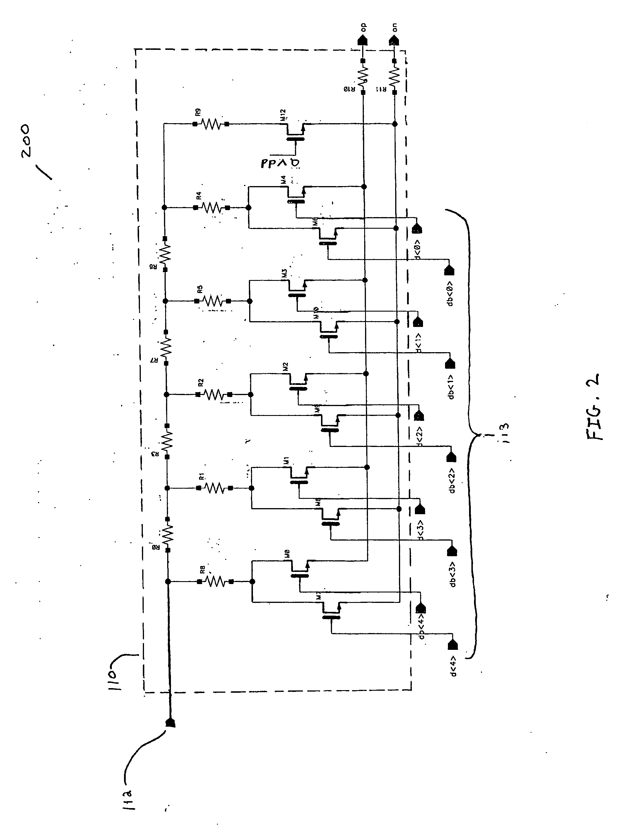
CROSS-REFERENCE TO RELATED APPLICATIONS [0001] This application claims the benefit of U.S. Provisional Application No. 60 / 565,534, filed Apr. 27, 2004, which is incorporated herein in its entirety by reference.BACKGROUND OF THE INVENTION [0002] 1. Field of the Invention [0003] The present invention relates to the field of capacitive sensing. In particular, the present invention is related to using a variable gain amplification system as one component to sense a change in physical phenomenon occurring at the terminals of a capacitive sensor. [0004] 2. Related Art [0005] Capacitive sensors can sense changes related to physical phenomenon (e.g., pressure, acceleration, proximity etc) by changing the capacitance between their terminals. By sensing this change in capacitance, the change in the physical phenomenon can be measured. Using conventional techniques, however, these measurements are not as accurate as needed. [0006] What is needed, therefore, is a method and system to more accur...

Claims


Application Information

Patent Timeline
Patent Type & Authority Applications(United States)
IPC IPC(8): G01D5/24G01L9/12G01P15/125H04L27/06
CPCG01D5/24G01P15/125G01L9/12
Inventor RANGANATHAN, SUMANTKWAN, TOM W.LI, HUNG-SUNG
Owner AVAGO TECH INT SALES PTE LTD
Why Eureka
Try Eureka