
Apparatus and method for readjustment of a sampling time in radio receivers

a radio receiver and sampling time technology, applied in the field of apparatus and a sampling time readjustment in the radio receiver, can solve the problems of noisy sampling time error signal emitted from the early/late correlator, sampling rate error generally has a sampling time error, etc., and achieve the effect of reducing the sampling ra

Inactive Publication Date: 2005-10-27
INTEL CORP
View PDF3 Cites 10 Cited by
  • Summary
  • Abstract
  • Description
  • Claims
  • Application Information

AI Technical Summary

Benefits of technology

[0011] The invention is directed to an apparatus for readjustment of a sampling time of a discrete-value received signal in a radio receiver, which has as little implementation complexity as possible and satisfies the requirements for filter quality and latency. The invention is also directed to a method which allows the advantages mentioned above.
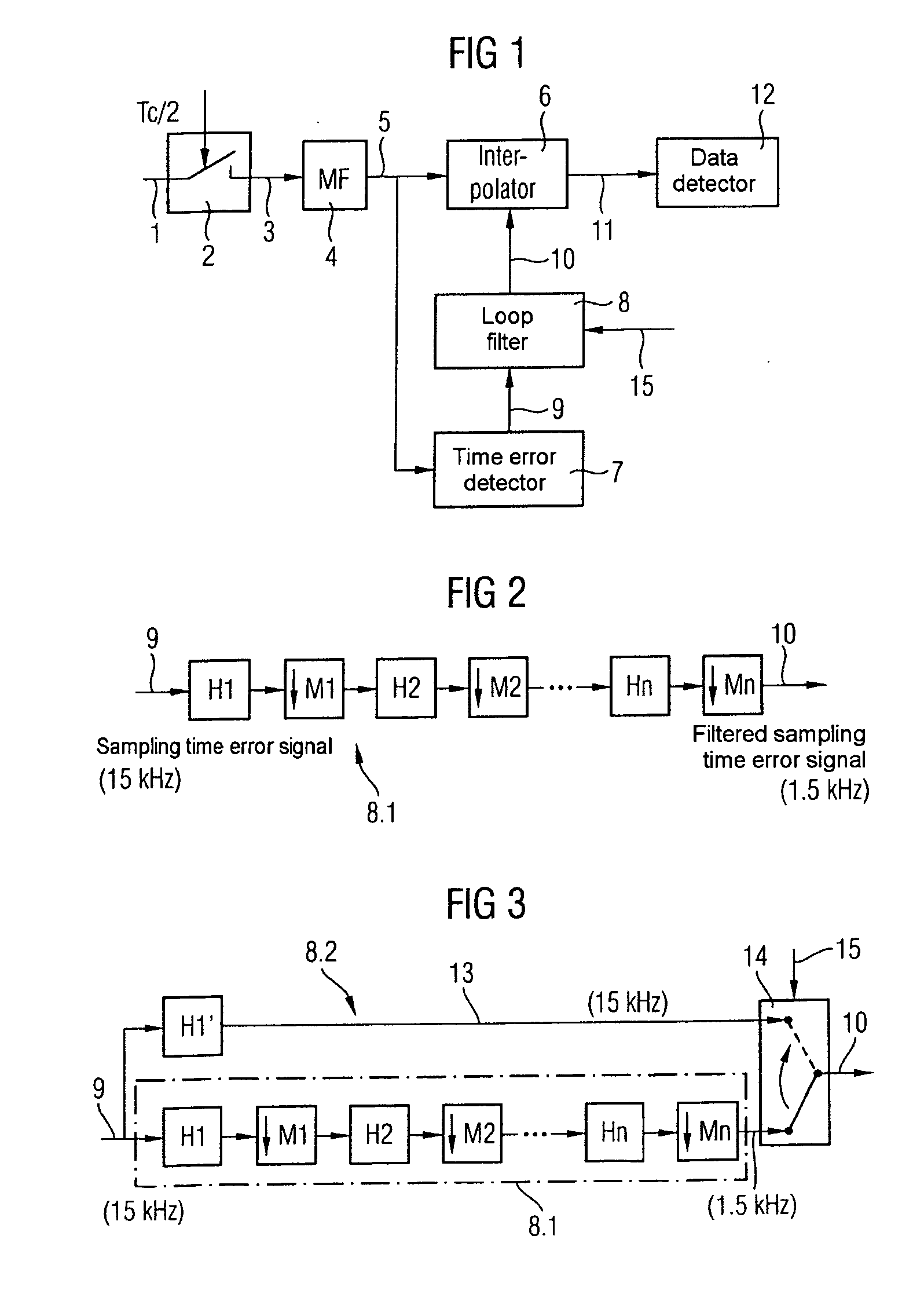
[0013] The use of a multi-rate filter is based on the discovery that, because of the narrow bandwidth of the sampling time error signal (for example 2 kHz for UMTS), its sampling rate (for example 15 kHz for UMTS) is generally much higher than is necessary. The sampling rate can thus be reduced during the filtering process without having to accept a deterioration in the filter characteristic.

Problems solved by technology

This means that the sampled discrete-value received signal generally has a sampling time error (discrepancy between the sampling time used and the optimum sampling time).
Since the early / late correlator determines the sampling time error signal from the received data, the sampling time error signal emitted from the early / late correlator is noisy.
This leads to fluctuations in the drive for the interpolator, which are undesirable.
The filtering of the sampling time error signal is subject to contradictory requirements.

Method used


Image

  • Apparatus and method for readjustment of a sampling time in radio receivers
  • Apparatus and method for readjustment of a sampling time in radio receivers
  • Apparatus and method for readjustment of a sampling time in radio receivers

Examples


Embodiment Construction

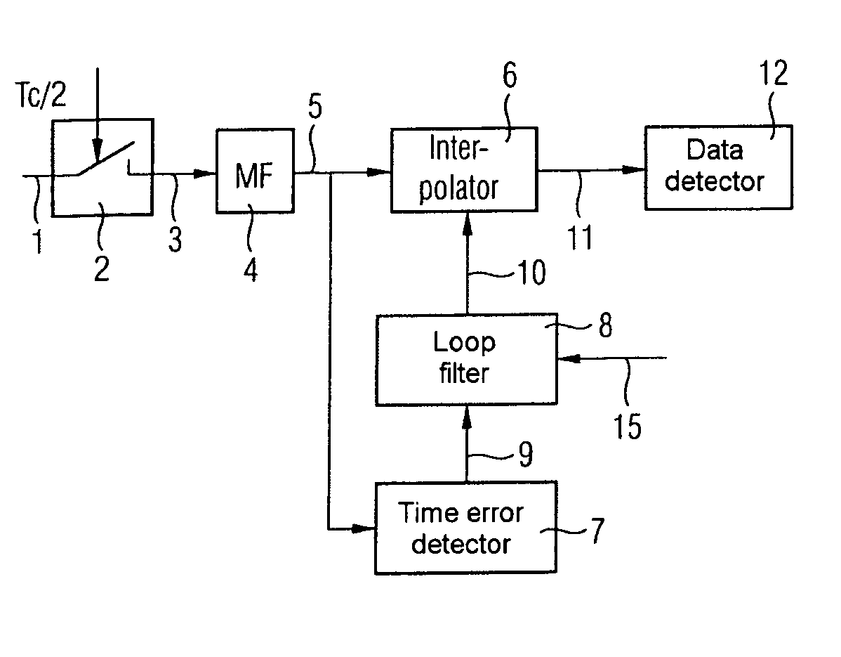
[0024] As can be seen from FIG. 1, an analog received signal 1 is sampled by an A / D converter 2 at twice the chip rate 2*Tc−1, and in the process is converted to a discrete-time and discrete-value received signal 3. Tc denotes the chip time period. The analog received signal 1 is in the intermediate-frequency range, or is in the form of a baseband signal. It is normally produced by means of a reception filter and a mixing stage from an analog antenna signal. The analog received signal 1 may be the I (in-phase) or Q (quadrature) component of the filtered and down-mixed antenna signal.

[0025] The discrete-value received signal 3 is passed to a matched filter MF 4, and is filtered therein. The output signal 5 from the matched filter 4 is passed both to an interpolator 6 and to a time error detector 7 (early / late correlator). The output of the time error detector 7 is connected to the input of a loop filter 8. The loop filter 8 optionally has a further input, via which a control signal ...


PUM


Abstract

An apparatus for readjustment of a sampling time in a radio receiver includes a means for determination of any sampling time error in a discrete-value received signal that emits a sampling time error signal. A filter arrangement is provided that includes a multi-rate filter that filters the sampling time error signal. A correction element receives the discrete-value received signal and the filtered sampling time error signal, and emits a discrete-value received signal whose timing has been corrected in accordance with the sampling time error.

Description

REFERENCE TO RELATED APPLICATIONS [0001] This application is a continuation of PCT / DE03 / 02963, which was not published in English, which claims the benefit of the priority date of German Patent Application No. DE 102 48 052.4, filed on Oct. 15, 2002, the contents of which both are herein incorporated by reference in their entireties.FIELD OF THE INVENTION [0002] The invention relates to an apparatus and a method for readjustment of a sampling time in a radio receiver. BACKGROUND OF THE INVENTION [0003] Since the signal processing in modern radio receivers is carried out digitally in the intermediate-frequency band or in baseband, the received analog signal must be sampled and digitized. This process is referred to as analog / digital (AD) conversion. The sampling frequency must, as is known, be chosen to be sufficiently high to satisfy the Nyquist condition. The optimum sampling time is governed by the time of maximum energy in a received information unit (bit or chip). This optimum s...

Claims


Application Information

Patent Timeline
Patent Type & Authority Applications(United States)
IPC IPC(8): H04B1/707
CPCH04B1/7085
Inventor BECKER, BURKHARDPAUL, STEFFENRUPRICH, THOMAS
Owner INTEL CORP
Learn More