
Image reading apparatus

Inactive Publication Date: 2005-10-27
FUJIFILM BUSINESS INNOVATION CORP
View PDF28 Cites 61 Cited by
  • Summary
  • Abstract
  • Description
  • Claims
  • Application Information

AI Technical Summary

Benefits of technology

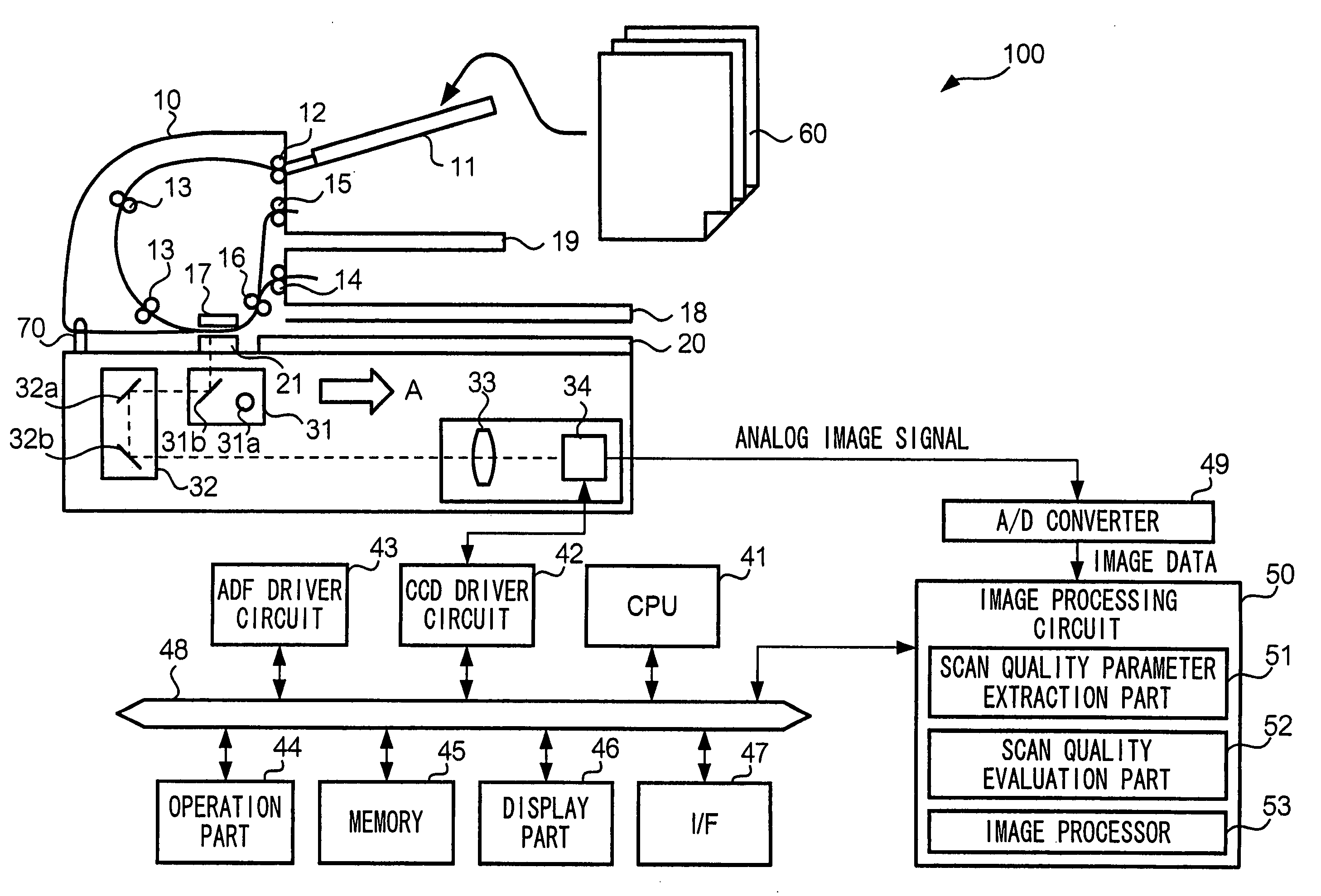
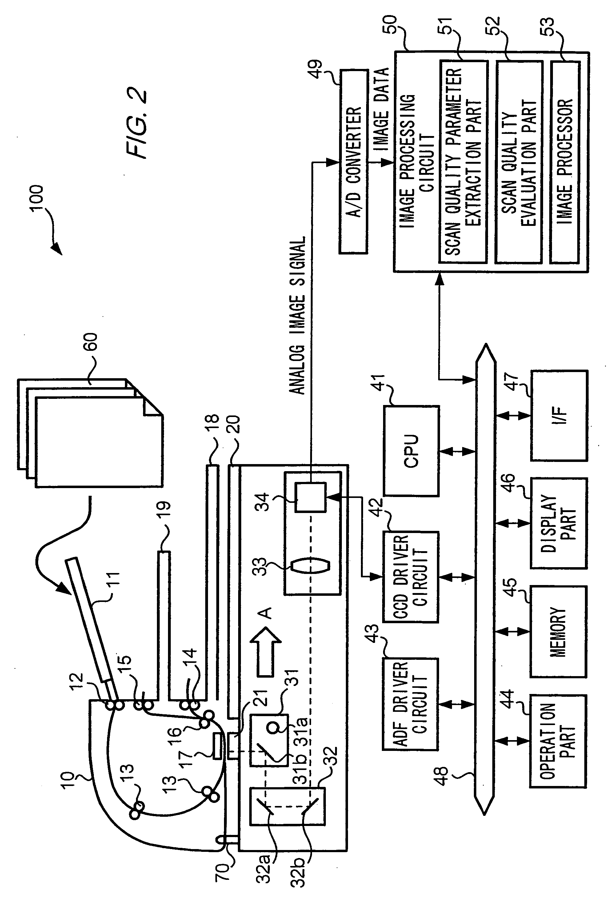
[0018] To address the above problems, the present invention provides a image reading apparatus equipped with a scan quality parameter extraction part that extracts scan quality parameters representing the quality of a scanned image from image data based on a scan error detection algorithm and; a scan quality evaluation part that determines whether a scan error occurs, based on the scan error detection algorithm and the scan duality parameters; and a notification part that notifies a result determined by the scan quality evaluation part to a user. With this image reading apparatus, it is possible to use automatic detection of scanning errors to attempt efficiency improvements in scanning work.

Problems solved by technology

Performing a scan of such documents using both multi level color and high resolution can end up consuming more resources than necessary, such as work time or data storage.
However, when the user inputs unsuitable operation parameters, leading to indistinct photographs and detailed characters and the like, there is the problem that the quality of the scanned image (henceforth, “scan quality”) ends up being reduced.
However, inspection by users is labor-intensive, and because it relies on the user, the quality or lack thereof for each user can be ambiguous, resulting in the problem of inconsistencies in judgment about the quality of scanned images, especially when there is more than one user, scanning many pages.
However, with the technique given in patent reference 1, the checking result is only presented as an image, and when performing a rescan, users are required to rescan after determining quality problems in the document, which is not efficient.
As well, the techniques given in patent references 2 and 3 evaluate the special characteristics of image output apparatus using statistical operations or test pattern scanning, but there remains a problem that the scanned images is not evaluated.
Furthermore, the scan errors that can be sensed using the image quality evaluation techniques given in patent reference 4 are very limited.
As well, there is also the problem that even in checking image data using present-day techniques, users may not improve their technical skills at all.

Method used


Image

  • Image reading apparatus
  • Image reading apparatus
  • Image reading apparatus

Examples


first embodiment

[0076]FIG. 7 is a flowchart showing the operations of scanner 100 according to the first embodiment. FIG. 8 shows an example of a display that informs the user of scan error detection results. The user first puts on platen glass 20 a sheet from the multi-page document 60, and after performing an operation such as selection of the scan mode, gives an instruction for scan to scanner 100 to by pressing the start button. Then, in the interior of scanner 100, image data corresponding to document 60 is generated (Step S301).

[0077] Scanner 100 executes on the scanned image at least one of the above scan error detection algorithms (Step S302). In the case of detecting a scan error as a result of applying a scan error detection algorithm (Step S303: YES), a signal representing the occurrence of a scan error and the identifier of the scan error detection algorithm is output from scan quality evaluation part 52 to CPU 41, as already explained. When CPU 41 receives the signal indicating that a...

third embodiment

[0094] In the present embodiment, the quality of the scanned image is not explained from the point of either good or bad; an explanation is given form the point that the quality of the scanned image is presented by digitization. Scan quality evaluation part 52 is further equipped with a function for computing numerical values that represent the quality of the scanned image. Specifically, memory part 45 stores scan quality index conversion table TB3 for converting scan quality parameters that have been input from scan quality parameter extraction part 51 into numerical values representing scan quality (hereafter, “scan quality indices”).

[0095] FIGS. 12(a)-(c) show examples of scan quality index conversion tables TB3. Memory part 45 records one or more of such tables. In scan quality index conversion table TB3, identifiers for identifying types of scan quality parameters (FIG. 9(a) “skew angle”, (b) “C / A”, and (c) “gradation range”) and scan quality parameter values are stored in cor...

fourth embodiment

[0105] For the present embodiment, scanner 100 has functions to automatically correct the scanned image when a scan error occurred. Scanner 100 scans a document and generates image data corresponding to the document scanned. Scan quality parameter extraction part 51 applies the above scan error detect ion algorithms to the image data generated, and outputs to scan quality evaluation part 52 the scan quality parameters. The operations explained so far are similar to those of the first through third embodiments

[0106] In the present embodiment, when detecting a scan error, scan quality evaluation part 52 determines whether the scan error must be corrected. To this end, scan quality evaluation part 52 reads out a correctibility table TB4 from memory part 45. In correctibility table TB4, identifiers that specify scan error detection algorithms are stored in correspondence with flags that indicate whether the scan error must be corrected. Specifically, skew is correctable by applying rot...


PUM


Abstract

An image reading apparatus has a scan quality parameter extraction part, a scan quality evaluation part and a notification part. The scan quality parameter extraction part extracts scan quality parameters representing the quality of a scanned image from image data based on a scan error detection algorithm. The scan quality evaluation part determines whether a scan error occurs, based on the scan error detection algorithm and the scan quality parameters. Also, the notification part notifies a result determined by the scan quality evaluation part to a user.

Description

BACKGROUND OF THE INVENTION [0001] 1. Field of the Invention [0002] The present invention concerns image reading apparatus. More specifically, it is concerned with image acquisition apparatus with functions to evaluate the image quality of scanned images. [0003] 2. Description of the Related Art [0004] Paper documents (documents, or copy) can be put into electronic form and saved by reading them by a scanner (scanning). In such circumstances, it is desirable that the digitized documents are complete copy of the original documents. For that purpose, where the color tone, resolution or the like are the main concern, it may be better to scan all documents using multi level color and at high resolution as well, but under real conditions the copy will be a mixture of color or monochrome, and the content of the text will be a mixture of characters and photography, and it is not necessarily any reason for scanning the entire document using multi level color and high resolution. Performing ...

Claims


Application Information

Patent Timeline
IPC IPC(8): H04N1/00G06V10/98
CPCG06K9/03G06V10/98
Inventor KIMURA, SHUNICHIKATO, MASAHIROIKEGAMI, HIROAKIASHIKAGA, HIDEAKIITONORI, KATSUHIKOSATAKE, MASANORIYOSHIMURA, HIROKI
Owner FUJIFILM BUSINESS INNOVATION CORP
Features
  • Generate Ideas
  • Intellectual Property
  • Life Sciences
  • Materials
  • Tech Scout
  • Unparalleled Data Quality
  • Higher Quality Content
  • 60% Fewer Hallucinations
Learn More