Metal matrix composite structures

a composite structure and metal matrix technology, applied in the field of metal matrix composite structure, can solve the problems of increasing the weight corresponding to the size increase, complex fabrication of a component entirely out of a metal matrix composite, and high cost of parts production, so as to increase the strength of the resulting structure and increase the structure weight

Inactive Publication Date: 2005-10-27
TOUCHSTONE RES LAB
View PDF16 Cites 5 Cited by
  • Summary
  • Abstract
  • Description
  • Claims
  • Application Information

AI Technical Summary

Benefits of technology

[0005] The invention is generally directed to sandwich-type structures where a lightweight core material is strengthened by opposing layers of a metal matrix composite material. With these structures, the strength of the resulting structure is significantly increased above the strength of the core material alone without significantly increasing the weight of the structure.

Problems solved by technology

This approach leads to an increase in weight corresponding to the increase in size.
The fabrication of a component entirely out of a metal matrix composite can be complicated requiring molds specifically designed to form the component.
Depending on the reinforcing material these parts can be expensive to produce.

Method used


Image

  • Metal matrix composite structures
  • Metal matrix composite structures
  • Metal matrix composite structures

Examples


Embodiment Construction

[0017] The invention is generally directed to a sandwich-type structure where a lightweight and possibly flexible core material has a metal matrix composite on opposing sides of the core material, thereby producing a sandwich structure that has greater strength and stiffness that that of the core material alone without a significant increase in overall weight.

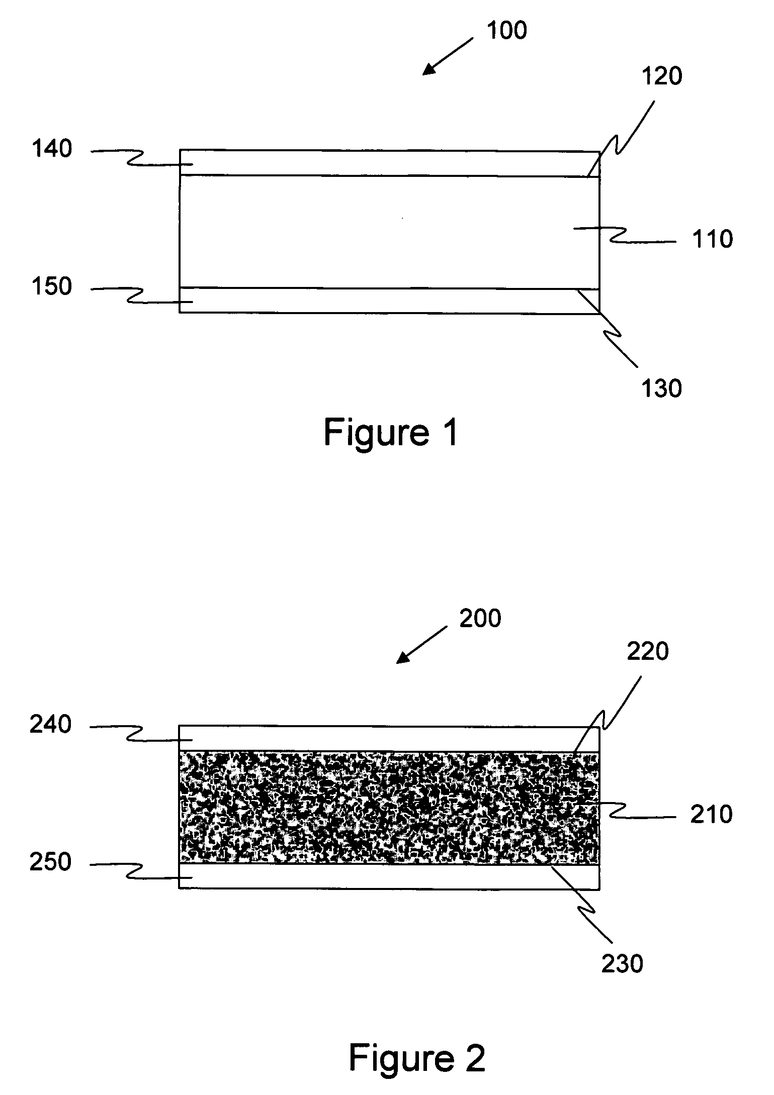
[0018] With reference now to FIG. 1, there is shown a metal matrix composite structure in accordance with an embodiment of the invention and given the reference numeral 100. The structure 100 has a core material 110 with first surface 120 and a second surface 130. A first metal matrix composite layer 140 is attached to the first surface 120 and a second metal matrix composite layer 150 is attached to the second surface 120. The first surface 120 and second surface 130 may be opposing surfaces as shown in FIG. 1 or they may be at any angle to one another including orthogonal to one another, depending on the application.

[0019] ...


PUM

PropertyMeasurementUnit
thicknessesaaaaaaaaaa
widthsaaaaaaaaaa
structureaaaaaaaaaa

Abstract

A lightweight, high strength structure is described where a core material has a first and second metal matrix composite layer on surfaces of the core material. A sandwich type structure may be formed. The core material may be a solid material, a foam, a honeycomb structure, or may be a channeled material. The metal matrix composite layers may include fiber reinforced metal matrix composites.

Description

CROSS-REFERENCE TO RELATED APPLICATIONS [0001] The present application is a continuation-in-part of and claims priority to U.S. application Ser. No. 09 / 882,096, filed Jun. 15, 2001, which is herein incorporated by reference in its entirety. Further, the present application claims priority to U.S. Provisional Patent Application No. 60 / 525,837, filed Dec. 1, 2003; U.S. Provisional Patent Application No. 60 / 526,100, filed Dec. 2, 2003; and U.S. Provisional Patent Application No. 60 / 526,101, filed Dec. 2, 2003, each of which are specifically herein incorporated by reference in their entirety.[0002] This invention was made with Government support under contract number DAAD19-01-2-0006 awarded by the Army Research Laboratory. The Government has certain rights in the invention.FIELD OF THE INVENTION [0003] The invention is generally directed to metal matrix composite structures. More particularly, the invention is directed to sandwich-type metal matrix composite structures. BACKGROUND OF T...

Claims


Application Information

Patent Timeline
Patent Type & Authority Applications(United States)
IPC IPC(8): B22F7/02B32B3/12B32B15/00B32B15/04C22C47/00C22C49/00
CPCB32B3/12B32B15/01C22C2204/00C22C49/00B32B15/04B32B3/20B32B5/18B32B15/20B32B2305/024B32B2311/24Y10T428/249927Y10T428/249929Y10T428/249971Y10T428/249974Y10T428/249986Y10T428/24999Y10T428/31678
Inventor JOSEPH, BRIAN E.MERRIMAN, DOUGLAS J.NOLTE, ROBERTROWE, MATTHEW M.
Owner TOUCHSTONE RES LAB
Why Eureka
Try Eureka