[0016] The present invention discloses a
golf club especially useful as a putter which: 1) maximizes clubhead planar
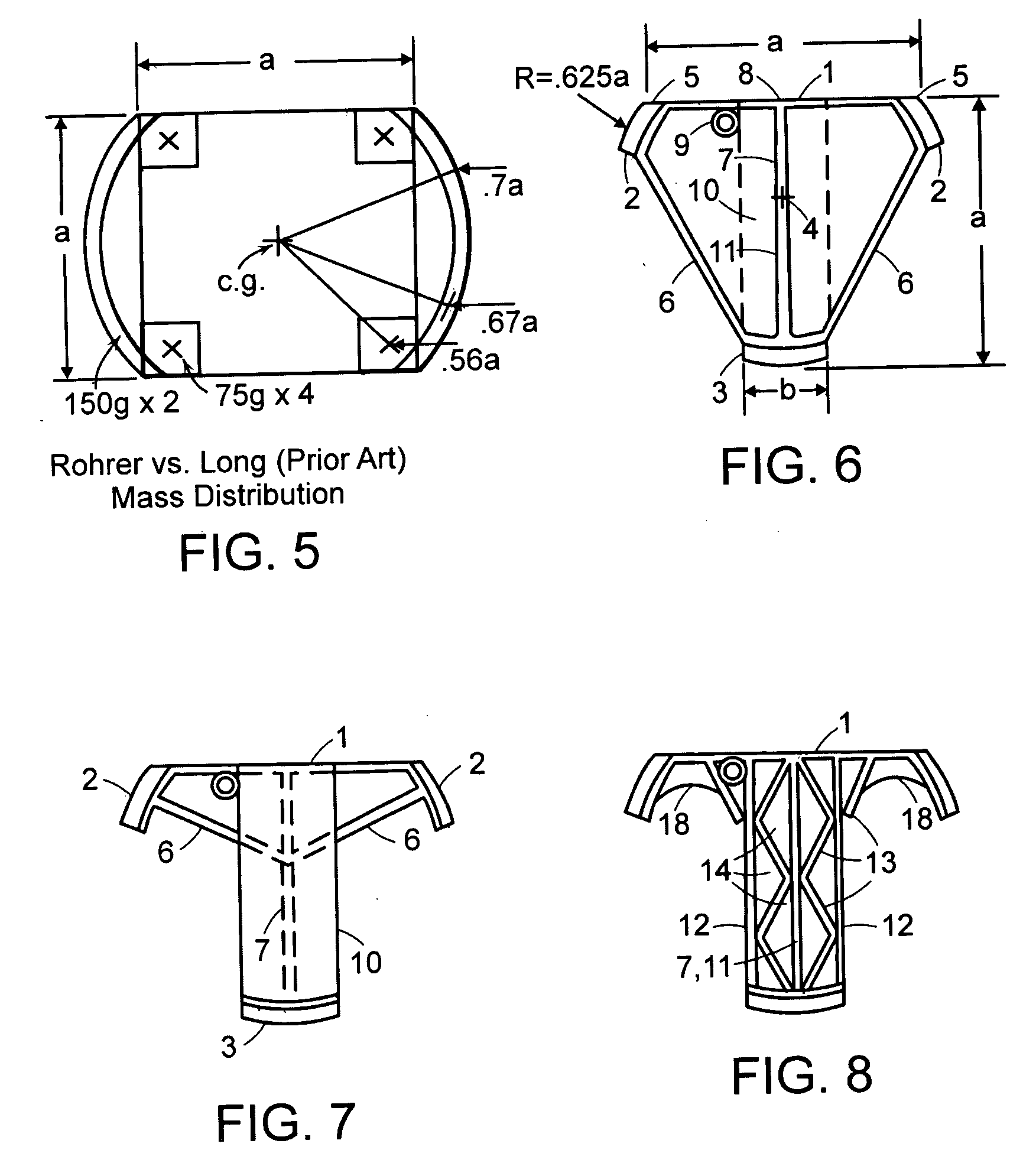
moment of inertia (MOICH) for a given maximum clubhead dimension and clubhead weight and in preferred embodiments, overall club or putter planar
moment of inertia (MOIP) by placing a majority of clubhead mass (in preferred embodiments over 70%) within one or more arcuate or three or more separate positions, approximately
equidistant from the clubhead
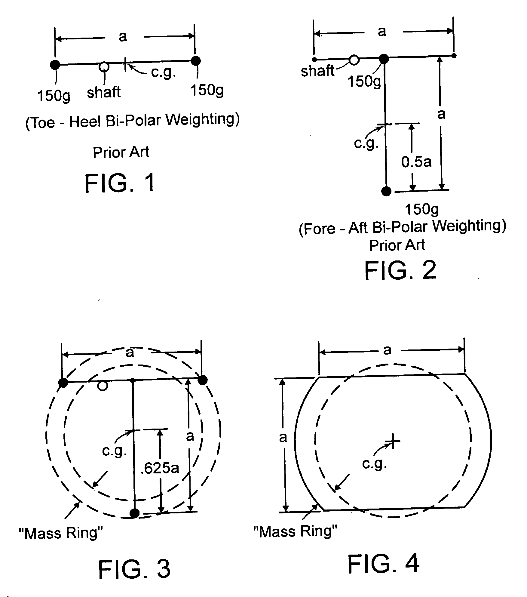
center of mass, and within a planar ring, the “
Mass Ring”, centered about the clubhead center of mass, the extremity or outside
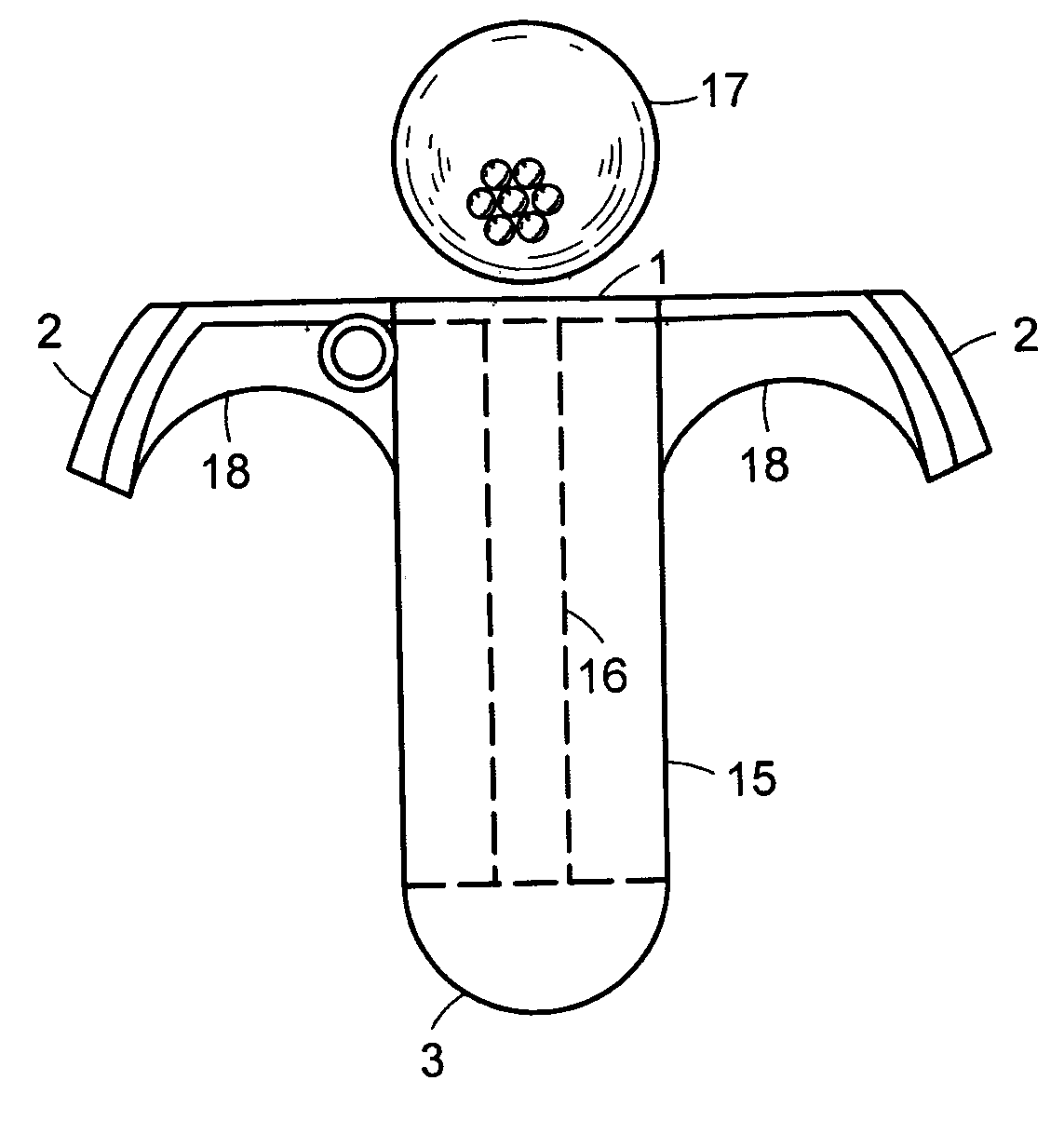
diameter of such ring, or other points of greatest width, approximately coincident with both ends of the putter striking face (excluding sharp corners which may be outside said mass ring) and the rear most positions of such putterhead, 2) provides the desirable high MOIP of 1) above along with enhanced feel by using rigid open truss members to put said majority of clubhead mass and the club shaft in rigid
solid communication with the central portion of the clubhead strike face thus minimizing undesirable
impact vibration within individual clubhead members. Undesirable
torsional vibration from miss-hits are reduced due to the extremely high MOICH and MOIP relative to clubhead weight and
maximum dimension, and 3) in some embodiments facilitates more accurate aim or sighting along the intended
target line by using an elongated
target line (axial) aligned Sighting Field, approximately the width of a
golf ball and at least ⅔ as long as the facewidth, and / or a narrow axial
Sight Line.
[0019] The present invention achieves high MOICH by putting most of the clubhead mass into a relatively narrow ring, the Mass Ring, approximately concentric around the clubhead center of mass. Weight size and location are adjusted to keep this weighting ring or Mass Ring concentric. The clubhead interior to this Mass Ring is mostly open or
void space which serves several purposes. Firstly, voids have no mass. Secondly, these void areas are not visible (you see green grass through the putterhead voids) thus allowing the golfer to better focus and aim with the axial Sighting Field or
Sight Line. Because the Mass Ring of the present invention is relatively narrow, and preferably green or other dark dull color, it does not distract focus from aim down the Sighting Field and
Sight Line. Likewise, those frame members rigidly and solidly connecting the weights to the putterface and shaft
mount outside the
Sight Line or Sighting Field, are thin in planar section, and likewise dull or dark
colored. The same elements of the present invention, therefore, allowing maximum MOICH and MOIP, namely the Mass Ring supported by a rigid high open area,
thin section, open (space) frame also provides superior putter aim or sighting. Should the USGA at any time allow dimensional changes or appendages on putterheads outside the Mass Ring
diameter of the present invention (a circle approximately concentric with the center of mass approximately intersecting the
toe and
heel extremities of the faceplate, or other points of greatest width, and the rear most portions of the putterhead, excluding sharp corners or projections of small mass), then the Mass Ring
diameter shall be extended and all other principles of the present invention shall apply.
[0021] Axial sighting or aim (down the target line) is superior to transverse sighting for most golfers. This is why
pool players and fire arms shooters site down the
pool cue or
gun barrel rather than transverse to it. Most putterheads are shallow front to back vs.
toe to
heel with short ineffective or non-existent Sighting Fields and Sight Lines. The predominant optical lines of most putterheads are transverse (parallel to the strikeface), forcing the golfer to draw an imaginary 90° line from the intended strikepoint on the strikeface through the ball to the target. The ball optically blocks the Sight Line making aim even more difficult.
[0023] The Sighting Field can be one
solid, preferably light
colored band, or single or multiple shapes (FIG. 16) such as ovals, circles, diamonds, hexagons, or combinations thereof. For more accurate aim, an elongated Sight Line is provided with or without the Sighting Field. This can be a solid line of contrasting color of 1 mm to 40 mm width down the center of the Sighting Field through the intended putterface strike point. Alternatively, the Sight Line can be multiple dots or sharp points on one or more of the above referenced shapes creating the Sighting Field (FIG. 16). Shapes with sharp centerline points (diamonds, arrows, hexagons) are preferable to rounded objects (circles or ovals), which later shapes preferably have a solid or dotted Sight Line through them to assist aim.

