Needle for medical use

Inactive Publication Date: 2005-10-27
SCITEC
View PDF18 Cites 5 Cited by
  • Summary
  • Abstract
  • Description
  • Claims
  • Application Information

AI Technical Summary

Benefits of technology

[0024] Further, because the tip portion of the inner needle is formed as a spherical crown portion, and the omnidirectionally spherical surface thereof comes into smooth contact with the living tissue, as described above, the surface of the blood vessel wall will not undesirably be damaged even when it is lightly rubbed with the spherical crown portion in searching for the location of the punctured hole in the surface of the blood vessel wall. Therefore, the front end portion of the inner needle can be smoothly inserted into the punctured hole and connected to the interior of the blood vessel, with practically no pains being given to the patient, and then the tip bore portion of the outer tube needle can also be smoothly inserted into the blood vessel, together with the main body portion of the inner needle, along the p

Problems solved by technology

However, with conventional medical puncture needles 1, 2, 5, as described above, a thick needle of 14 to 19 gage in size diameter is used in order to secure the blood flow rate required for hemodialysis (200 to 300 ml/min), and thus a problem that the patient is forced to endure the pains involved in creating a puncture (boring pains) at every dialysis session carried out two or three times a week, for example.
Further, because the tip is sharp, a mere touch with the needle has tended to cause wrong puncture, and thus puncture troubles due to such wrong puncture, such as subcutaneous bleeding, could not have been effectively avoided, giving patients pain.
Further, the repetition of puncturing scrapes off and thus damages the tissue at the puncture site in the so-called blood accesses, harden

Method used


Image

  • Needle for medical use
  • Needle for medical use
  • Needle for medical use

Examples


first embodiment

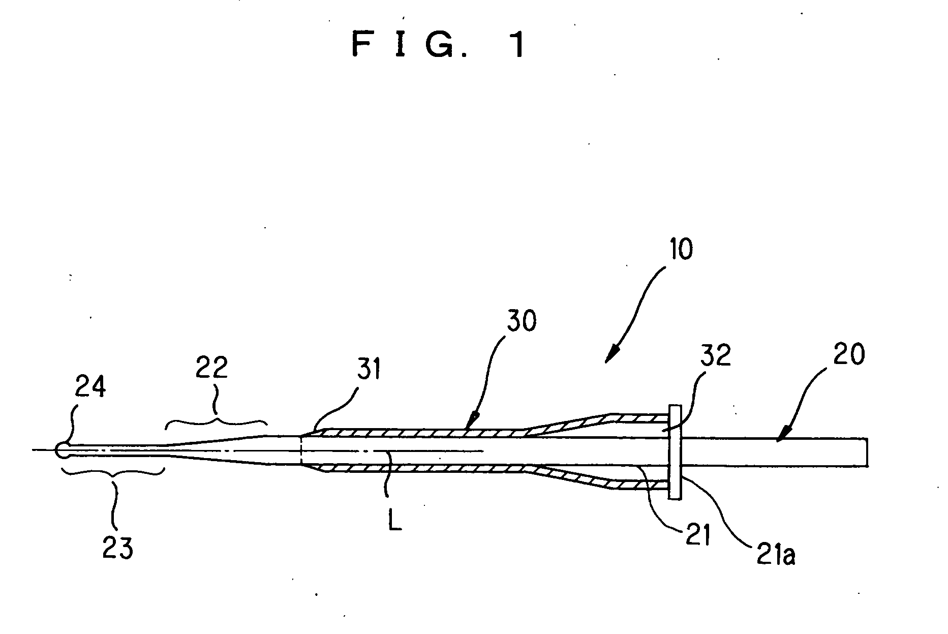
[0038]FIG. 1 to FIG. 5 show the present invention.

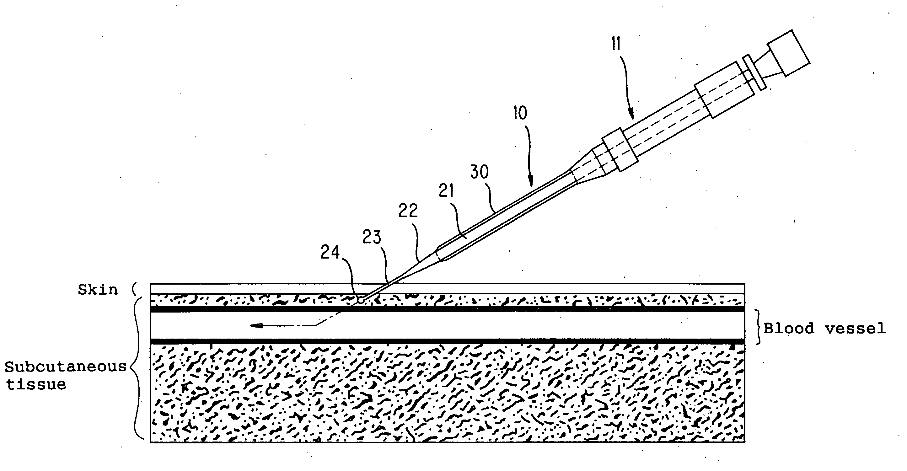
[0039] As shown in FIG. 1, a medical needle 10 is used by inserting an inner needle 20 into an outer tube needle 30 with integrally combining them with each other. Herein, an application where the medical needle 10 is connected to each of the blood accesses for the arterial side and for the venous side in a patient's arm during hemodialysis will be used for description.

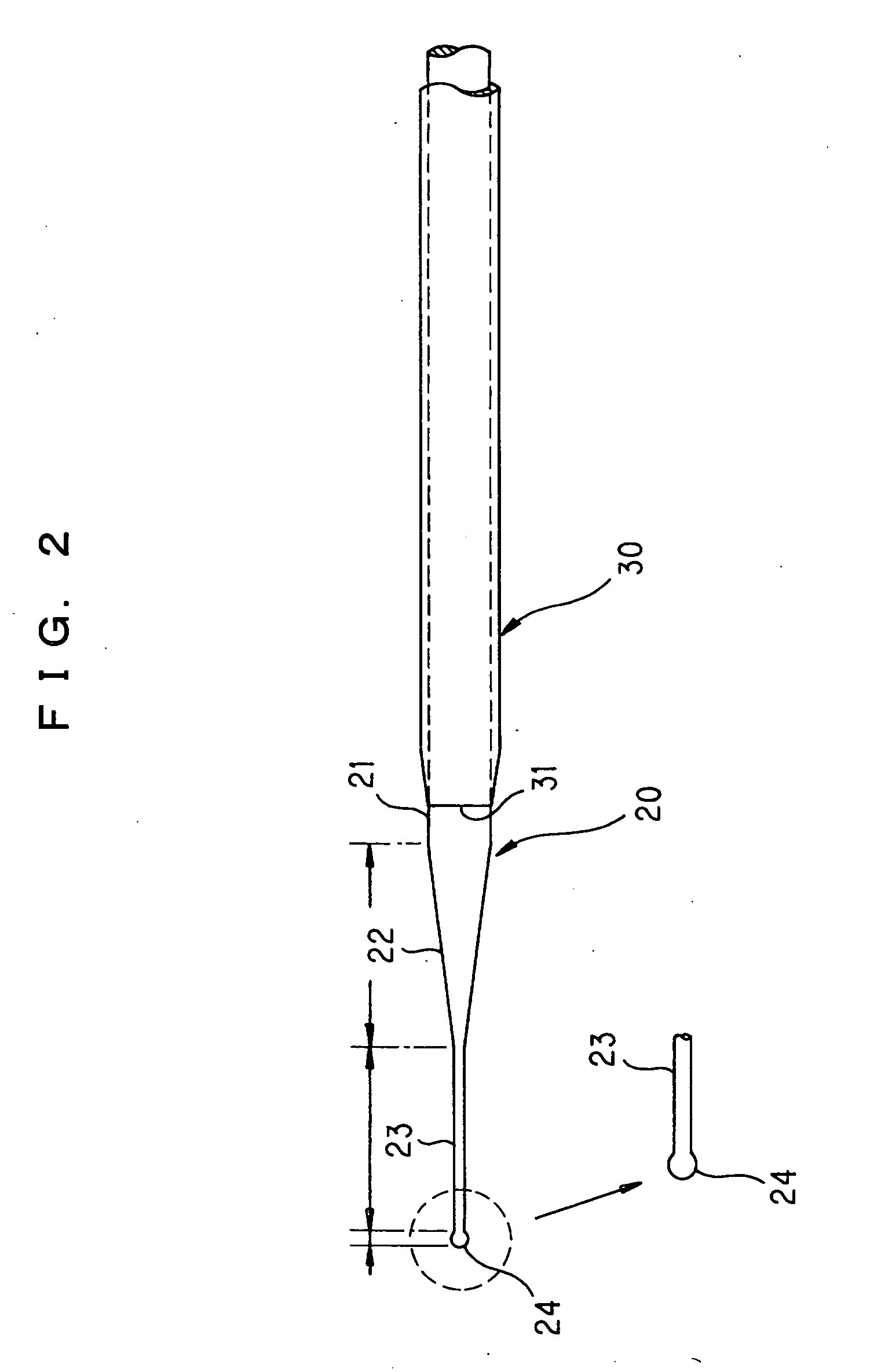
[0040] As shown in FIG. 3, the inner needle 20 is a solid rod-like needle made of a metal such as stainless steel or titanium, for example, and provides a portion which, in using the medical needle 10, is first inserted into a punctured hole which was once formed in a patient's arm. The word “solid rod-like” used here means that the inner needle 20 is not structured as a tubular rod, which has a space inside it, but as a solid rod, having no space inside it. In addition, the term “rod-like” is used as opposed to the term “tubular,” and it is needless to say that the t...

second embodiment

[0057]FIG. 6 shows the present invention.

[0058] In the second embodiment, the diameter of the spherical crown portion 24A is adapted to be still larger than the outside diameter of the spherical crown portion 24 according to said first embodiment. Specifically, the diameter of the spherical crown portion 24A may be 1.2 to 1.3 mm, for example, while the outside diameter of a small-diameter portion 23 is 0.72 mm (22 G).

[0059] Thereby, the spherical surface of the spherical crown portion 24A can be brought into contact with the living tissue over a wider angular range, and the small-diameter portion 23 can advance more smoothly after the spherical crown portion 24A is inserted into the punctured hole. The portions similar to those of the first embodiment are provided with the same reference signs to avoid duplication of the explanations.

third embodiment

[0060]FIG. 7 shows the present invention.

[0061] In the third embodiment, the diameter of the spherical crown portion 24B is adapted to be approximately equal to the outside diameter of said small-diameter portion 23, and the diameter of the spherical crown portion 24B may be 0.72 mm, for example, while the outside diameter of the small-diameter portion 23 is 0.72 mm (22 G).

[0062] Thereby, in the third embodiment, the spherical crown portion 24B can be easily machined, which allows cost reduction, and the spherical crown portion 24B can be more smoothly inserted into the punctured hole. The portions similar to those of the first embodiment are provided with the same reference signs to avoid duplication of the explanations.

[0063]FIG. 8 shows a fourth embodiment of the present invention.

[0064] In the fourth embodiment, said inner needle 20a is provided with a through hole 25 which substantially passes through the axis over the entire length thereof. The through hole 25 has a very fi...


PUM


Abstract

A medical needle which can greatly reduce the pains involved in creating a puncture, avoid subcutaneous bleeding and damage to blood vessel walls by preventing wrong puncture, eliminate the possibility that coring may occur, causing further damage to the living tissue and a part of the living tissue to flow into a blood vessel, can prevent occurrence of infection accidents due to wrong puncture, and thus can assure a high level of safety of health-care workers.
A medical needle (10), comprising a solid rod-like inner needle (20) which is inserted into the living tissue, and a hollow cylindrical outer tube needle (30) which is inserted into the living tissue together with the inner needle (20), with the inner needle (20) being inserted thereinto, and is retained in the living tissue after the inner needle (20) is removed, wherein the tip portion of the inner needle (20) extending out of the front end bore of said outer tube needle (30) is formed as a spherical crown portion (24) which is capable of being inserted along a punctured hole previously formed in the living tissue so as not to damage the lumen of the punctured hole.

Description

FIELD OF THE INVENTION [0001] The present invention relates to medical treatment in a broad sense, more particularly to a medical needle comprising an inner needle which is inserted into living tissue, and a hollow cylindrical outer tube needle which is inserted into the living tissue together with the inner needle, with the inner needle being inserted thereinto, and is retained in the living tissue after the inner needle is removed; and still more particularly to a medical needle inserted into a blood vessel in the human body for use in a blood circuit during hemodialysis. BACKGROUND [0002] Conventionally, to extracorporeally circulate the blood during hemodialysis, a method with which two medical puncture needles of 14 to 19 gauge having a sharp tip is inserted into so-called blood accesses provided in a patient's arm for securing routes for the arterial side and for the venous side, and through a blood circuit including these routes, drawing the blood out of the body has been wid...

Claims


Application Information

Patent Timeline
IPC IPC(8): A61M5/158A61M25/00A61M25/06
CPCA61M5/158A61M2025/0656A61M25/065A61M25/0612
Inventor SHIBATA, TAKERU
Owner SCITEC
Why Eureka
Try Eureka