Performing high-speed events ''on-the-fly'' during fabrication of a composite structure by automated fiber placement

a technology of composite structure and fiber placement, which is applied in the direction of electrical programme control, program control, instruments, etc., can solve the problems that the components of the automated fiber placement machine which perform and control the cut/add process are incapable of instantaneously cutting or adding a tow to the band of material, described above, and the operation of cutting/adding is also encountered

Active Publication Date: 2005-10-27
INGERSOLL MACHINE TOOLS
View PDF9 Cites 54 Cited by
  • Summary
  • Abstract
  • Description
  • Claims
  • Application Information

AI Technical Summary

Benefits of technology

[0010] The invention provides an improved method and apparatus for performing a high-speed event in an automated fiber placement process by initiating the high-speed event prior to the fiber placement head reaching a location along a tool path of the fiber placement head at which it is desired to have the high-speed event completed.

Problems solved by technology

The components of the automated fiber placement machine which perform and control the cut / add process are incapable of instantaneously cutting or adding a tow to the band of material, due to inherent and unavoidable lag times or other latencies in the operation of mechanical, hydraulic, pneumatic, or electrical actuation and control components of the automated fiber placement machine.
These unavoidable and inherent latencies result in the end of a cut or added tow often being positioned well outside of the tolerances required for constructing the composite structure where on-the-fly cut / add is attempted at full operating speed using prior fiber placement machines.
The problems described above, with regard to cut / add operations, are also encountered in other operations performed at high-speed on-the-fly during fabrication of a composite structure, such as changing tension, temperature, or pressure applied on a tow or the material band during automated fiber placement.

Method used


Image

  • Performing high-speed events ''on-the-fly'' during fabrication of a composite structure by automated fiber placement
  • Performing high-speed events ''on-the-fly'' during fabrication of a composite structure by automated fiber placement
  • Performing high-speed events ''on-the-fly'' during fabrication of a composite structure by automated fiber placement

Examples


Embodiment Construction

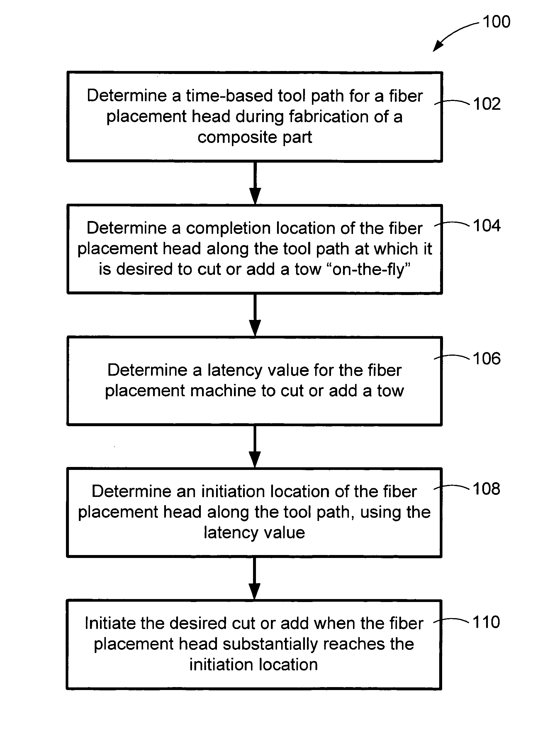
[0020]FIG. 1 shows an exemplary embodiment of a method 100, according to the invention for cutting and adding tows on-the-fly in an automated fiber placement process, using a fiber replacement head of a fiber replacement machine for fabricating a composite structure. The method 100 includes determining a time-based tool path for a fiber replacement head during fabrication of a composite part, as shown by block 102 in FIG. 1. A completion location of the fiber replacement head along the tool path, at which it is desired to cut or add a tow on-the-fly is also determined, as shown at block 104 of FIG. 1. A latency value for the fiber placement machine to cut or add a tow, is also determined, as shown at block 106 of FIG. 1. The latency value takes into account theoretical and empirical information reflecting time lags and other inherent and unavoidable delays in operation of mechanical, hydraulic, pneumatic, electrical, etc., components and systems of the automated fiber placement mach...


PUM

PropertyMeasurementUnit
speedaaaaaaaaaa
pressureaaaaaaaaaa
widthaaaaaaaaaa

Abstract

An apparatus and method are provided for performing a high-speed event, such as a cut/add of a tow, in an automated fiber placement process, by initiating the high-speed event prior to a fiber placement head reaching a location along a tool path of the fiber placement head at which it is desired to have the high-speed event completed.

Description

CROSS-REFERENCE TO RELATED PATENT APPLICATIONS [0001] This patent application claims the benefit of U.S. Provisional Patent Application No. 60 / 563,921, filed Apr. 21, 2004, the teachings and disclosure of which are hereby incorporated in their entireties by reference thereto.FIELD OF THE INVENTION [0002] This invention is related to the use of automated tape-laying machines for fabrication of composite structures, and more particularly to performing high-speed events, such as cutting or adding tows, increasing tow tension, or changing pressure or heat applied during fiber placement, “on-the-fly.”BACKGROUND OF THE INVENTION [0003] Automated fiber placement is a process that is widely used for fabricating composite structures using pre-impregnated composite materials, such as carbon fiber, fiber glass and Kevlar. The materials, for use in automated fiber placement, typically take the form of a strip or yarn of composite material impregnated with a resin. [0004] During automated fiber ...

Claims


Application Information

Patent Timeline
Patent Type & Authority Applications(United States)
IPC IPC(8): B29C70/38G05B19/18G05B19/4099
CPCB29C70/382B29C70/545G05B2219/49021G05B2219/45238G05B19/4099
Inventor OLDANI, TINOJARVI, DANIEL
Owner INGERSOLL MACHINE TOOLS
Why Eureka
Try Eureka