Sensor element

Inactive Publication Date: 2005-11-03
ROBERT BOSCH GMBH
6 Cites 2 Cited by

AI-Extracted Technical Summary

Problems solved by technology

The heater and the layers adjacent to the heater are exposed during operation to high mechanical stresses, which result from temperature fluctuations and the temperature gradients occurring within the layers.
When a heating voltage is applied, the voltage drop in the heater area may cause mobile ions such as sodium ions...

Benefits of technology

[0006] The sensor element according to the present invention has the advantage over the ...

Abstract

A layered sensor element used in a gas measuring sensor for measuring a physical property of a measuring gas, preferably for determining the temperature of the measuring gas or the concentration of a component of the measuring gas. The sensor element contains a wave-form heater, which is embedded in a porous heater insulation. At least one separating element having a lower porosity than the porous heater insulation is provided between two adjacent sections of the wave-form heater.

Application Domain

Electric heatingMaterial electrochemical variables

Technology Topic

PhysicsPorosity +2

Image

  • Sensor element
  • Sensor element

Examples

  • Experimental program(1)

Example

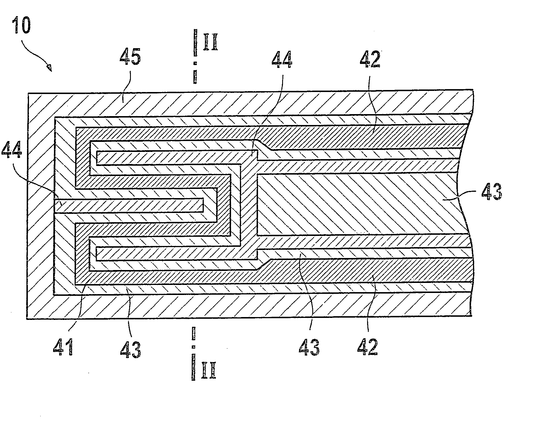
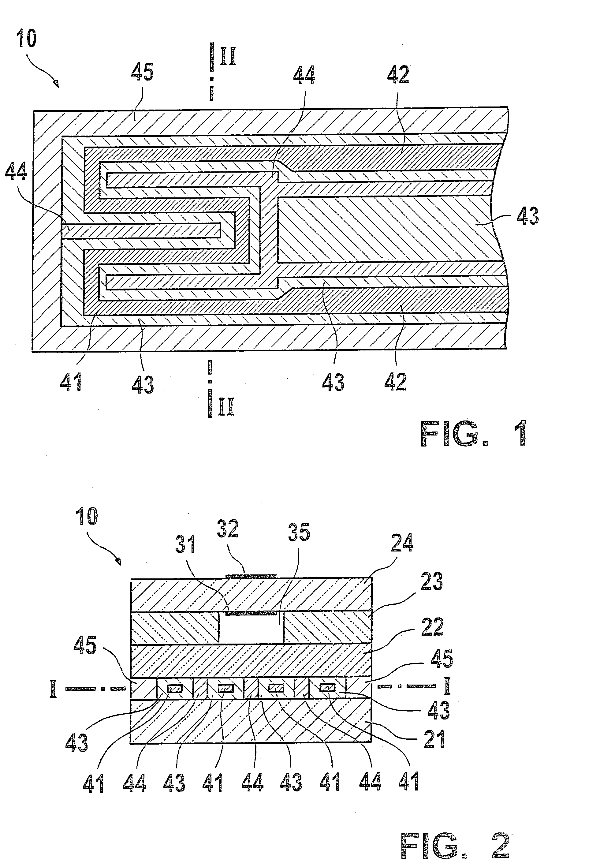
[0013]FIG. 1 and FIG. 2 show as an exemplary embodiment of the present invention, a sensor element 10 having a first solid electrolyte sheet 21, a second solid electrolyte sheet 22, a third solid electrolyte sheet 23, and a fourth solid electrolyte sheet 24.
[0014] A reference gas space 35 containing a reference gas is formed in third solid electrolyte sheet 23. For this purpose, reference gas space 35 is connected to the surrounding atmosphere via a channel extending longitudinally through sensor element 10 and an opening on the terminal side. A first electrode 31 is situated in reference gas space 35 on fourth solid electrolyte sheet 24. A second electrode 32 is provided on the external surface of fourth solid electrolyte sheet 24 opposite first electrode 31. First and second electrodes 31, 32 and fourth solid electrolyte sheet 24 in the area of the two electrodes 31, 32 form an electrochemical cell.
[0015] A wave-form heater 41 is situated between first and second solid electrolyte sheets 21, 22. Two heater leads 42 connect heater 41 to a circuit (not illustrated), situated outside of sensor element 10, which is able to apply a voltage (heating voltage) between the two heater leads 42. Heater 41 and heater leads 42 are fully surrounded by a porous heater insulation 43. The porosity of heater insulation 43 is approximately 15% by volume. In the layer of heater 41, heater insulation 43 is laterally fully surrounded by a sealing frame 45, which seals heater insulation 43 against the gas surrounding sensor element 10.
[0016] Wave-form heater 41 has four sections which extend parallel to the longitudinal axis of sensor element 10. The four sections are connected by three shorter sections perpendicularly to the longitudinal axis of sensor element 10. Separating elements 44 having a porosity of 4% by volume are provided between the adjacent sections of heater 41. Separating elements 44 are also provided between heater lead 42 and between heater lead 42 and a section of heater 41 adjacent to heater lead 42.
[0017] Separating elements 44 are at a distance from heater 41, so that separating elements 44 and heater 41 are separated by porous heater insulation 43. Separating elements 44 are situated in such a way that ion wandering between the different sections of heater 41 is prevented. Separating elements 44 are situated in particular in areas in which there is a high voltage differential between two sections of heater 41 when heating voltage is applied, because intensive ion wandering may occur in these areas in particular. Furthermore, ion wandering is enabled by high temperatures. Therefore, it is particularly important that separating elements 44 are provided in the hot areas of sensor element 10, in particular in the area of heater 41.
[0018] Heater 41 and heater leads 42 are made of platinum and a ceramic support structure. Porous heater insulation 43 and separating elements 44 are essentially made of aluminum oxide.
[0019] In a further exemplary embodiment (not illustrated) of the present invention, the heater is situated in a broadband lambda sensor, which includes an electrochemical pump cell and an electrochemical Nernst cell. The structure and mode of operation of a broadband lambda sensor of this type are described, for example, in German Patent Application No. DE 198 53 601 or in “Automotive Electronics Handbook,”2nd Ed., 1999, Publisher: Ronald K.
[0020] Jurgen, McGraw-Hill, Section 7, and the documents cited therein.
[0021] The present invention is not limited to the form of the heater illustrated in the exemplary embodiment and may be applied to any other forms of the heater. Furthermore, the present invention may be applied to any sensor element having a layered structure and a heater.

PUM

no PUM

Description & Claims & Application Information

We can also present the details of the Description, Claims and Application information to help users get a comprehensive understanding of the technical details of the patent, such as background art, summary of invention, brief description of drawings, description of embodiments, and other original content. On the other hand, users can also determine the specific scope of protection of the technology through the list of claims; as well as understand the changes in the life cycle of the technology with the presentation of the patent timeline. Login to view more.
Why Eureka
Try Eureka