
Integrated heat pump hot water unit

A technology for integrating heat pumps and hot water units, applied to fluid heaters, mechanical equipment, engine components, etc., can solve the problem of damage to internal circuit components of heat pump boxes and incubators, erosion of bottoms of heat pump boxes and incubators, and reduction of heat pump boxes and heat preservation The service life of the box and other issues

Active Publication Date: 2020-08-28
浙江康都节能科技有限公司
View PDF9 Cites 2 Cited by
  • Summary
  • Abstract
  • Description
  • Claims
  • Application Information

AI Technical Summary

Problems solved by technology

[0004] The above existing technical solutions have the following defects: in some areas, in order to ensure the safety of the use of the heat pump water heater unit, the heat pump water heater unit is usually installed on the open-air balcony; when encountering continuous rainfall, the balcony will inevitably appear. Water accumulation: Once the accumulated water overflows the feet 1 and 2 of the above-mentioned heat pump hot water unit, the bottom of the heat pump box and the insulation box will be soaked in the water, and the water will not only cause erosion to the bottom of the heat pump box and the insulation box , and once the accumulated water enters the inside of the heat pump box and the incubator, it will also damage the circuit components inside the heat pump box and the incubator, reducing the service life of the heat pump box and the incubator

Method used


Image

  • Integrated heat pump hot water unit
  • Integrated heat pump hot water unit
  • Integrated heat pump hot water unit

Examples


Embodiment Construction

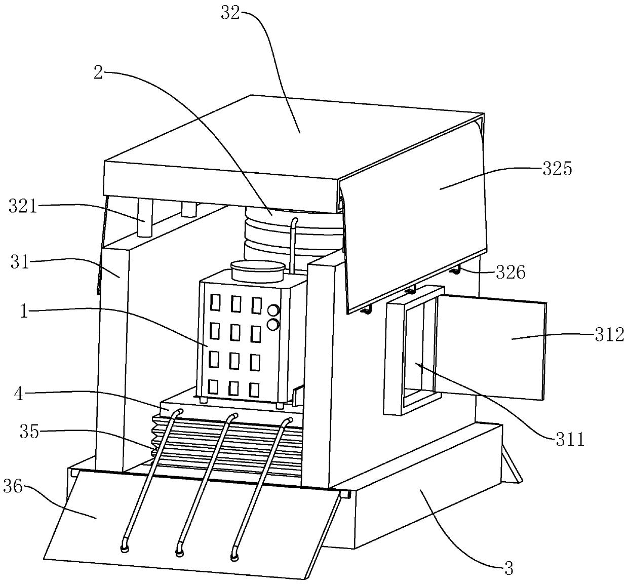
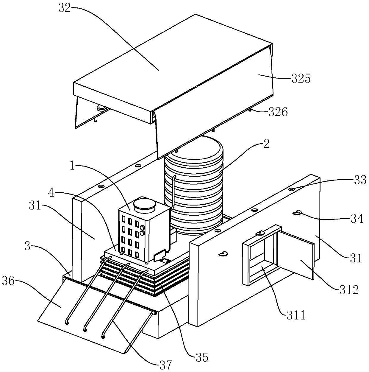
[0034] The present invention will be described in further detail below in conjunction with the accompanying drawings.

[0035] This embodiment discloses an integrated integrated heat pump water heater unit, such as figure 1 , figure 2 As shown, it includes a machine base 3 located at the bottom, and the center of the machine base 3 forms an installation groove with an opening facing upwards. A lifting platform 4 placed horizontally is installed in the installation groove. Placed air energy heat pump 1 and thermal insulation water tank 2. The circulation and interaction of hot water between the air source heat pump 1 and the thermal insulation water tank 2 is realized through pipes, and a water pump is arranged on the pipes to realize the transportation of hot water.

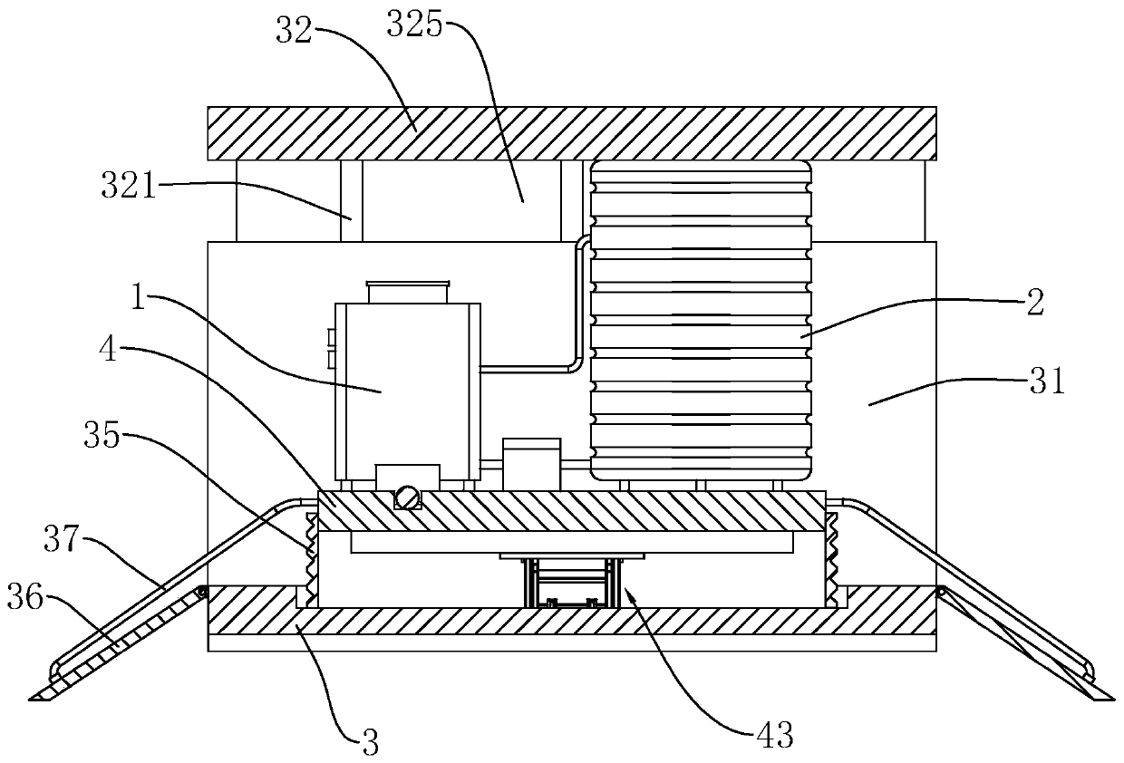
[0036] Such as image 3 , Figure 4 As shown, two groups of elevating mechanisms 43 that are cross-hingedly arranged are installed below the elevating platform 4. One end of the top of the elevating mechanis...


PUM


Abstract

The invention relates to an integrated heat pump hot water unit, and relates to the technical field of heat pump hot water units. The integrated heat pump hot water unit comprises an air energy heat pump, a heat insulation water tank and a machine base, wherein the air energy heat pump and the heat insulation water tank communicate through a pipeline; a lifting platform capable of lifting in the vertical direction is arranged on the machine base; the air energy heat pump and the heat insulation water tank are fixedly arranged on the top part of the lifting platform; limiting plates symmetrically arranged on the front side and the rear side of the lifting platform are further fixedly arranged on the machine base; a ceiling located above the air energy heat pump and the heat insulation watertank is arranged between the two limiting plates; a plurality of sliding rods toward the limiting plates are arranged on the bottom part of the ceiling; a plurality of sliding chutes with openings toward the sliding rods are formed in the limiting plates; and the sliding rods are inserted from the openings in the upper ends of the sliding chutes and are slidably arranged on the limiting plates inthe height directions of the sliding chutes. The integrated heat pump hot water unit provided by the invention has the effect of realizing the height adjustment on the unit to prevent flooding so asto prolong the service life of the unit.

Description

technical field [0001] The invention relates to the technical field of heat pump water heating units, in particular to an integrated integrated heat pump water heating unit. Background technique [0002] The heat pump water heater is a high-efficiency heat energy lifting and transferring device based on the reverse Carnot cycle. It uses a small amount of electric energy as power, and uses refrigerant as a carrier to continuously absorb low-grade heat energy in the air and convert it into sustainable energy. The high-grade heat energy utilized is then released into the water that needs to be heated to produce domestic hot water, which is then delivered to users through hot water pipelines. [0003] In the prior art, the Chinese patent with the authorized announcement number CN208504740U discloses a heat pump hot water unit, which includes a hot water unit body. The hot water unit body includes a heat pump box. A bracket is arranged on the top of the heat pump box. There is a...

Claims


Application Information

Patent Timeline
IPC IPC(8): F24H4/02F24H9/06B66F7/06B66F7/08F16J15/52
CPCB66F7/065B66F7/085F16J15/52F24H4/02F24H9/06
Inventor 徐利剑王少畅
Owner 浙江康都节能科技有限公司
Learn More