Quick disconnect bipod mount assembly with adjustable and lockable tilt, pan and cant controls

a quick disconnect and control technology, applied in the direction of machine supports, ammunition loading, other domestic articles, etc., can solve the problems of inability to consistently hold a firearm in a set position without wavering, bulky, inconvenient and difficult to use, and the ability of the bipod to mount, so as to achieve the effect of easy respons

Active Publication Date: 2005-11-03
KENG +1
View PDF32 Cites 97 Cited by
  • Summary
  • Abstract
  • Description
  • Claims
  • Application Information

AI Technical Summary

Benefits of technology

[0012] The present invention comprises a bipod-mounting device for mounting a bipod support to a forearm stock of a firearm, and permitting the user or shooter to selectively allow panning, tilting and canting. The bipods of the present invention is designed to control these three types of motion in a manner which lets the shooter easily respond to changing situations when in the field.
[0020] With the bipod of the present invention mounted, the shooter can shoulder the rifle and steady him or herself on a selected surface or terrain feature, placing the bipod feet on the surface. For shooters having their right eye as their dominant eye and right hand as their dominant hand, the left or non-dominant hand is then free to work the tilt / pan control and the cant / rotate control which are preferably located on the left side of the bipod frame. When tracking a moving target, the user can select an unlocked state for the tilt / pan control thereby allowing the firearm muzzle to move horizontally or laterally in a panning motion and vertically in a tilting motion. Alternatively, the user can actuate the locked state for the tilt / pan control, thereby locking the bipod frame to prevent the firearm muzzle from moving horizontally or laterally in a panning motion or vertically in a tilting motion.
[0021] When adapting to unlevel surfaces, the user can also select an unlocked state for the cant / rotation control, thereby allowing the firearm to rotate around the axis of the mounting post (preferably situated to be substantially parallel to the firearm's bore) in a canting motion defining a left or right arc, as needed. Alternatively, the user can actuate the locked state for the cant / rotation control, thereby locking the bipod frame to prevent the firearm from rotating around the axis of the mounting post in a canting motion.
[0022] The shooter can thereby selectively control panning, tilting and canting motions in response to changing situations when in the field.

Problems solved by technology

Most shooters are not able to hold a firearm consistently in a set position without wavering, especially after the onset of fatigue resulting from strain on the shooter due to the size and weight of the firearm.
Early bipod and tripod supports typically were somewhat crude strands that generally were bulky, inconvenient and difficult to use and typically were not easily adjustable.
One problem with conventional bipods has been the ability of the bipod to mount to most firearms without requiring the use of special mounting tools and the machining or modification of the firearm stock to accommodate the bipod.
Additionally, most bipods are not designed for quick and easy attachment and release of the bipod from the firearm stock.
However, these bipod mounts do not provide for the quick-release of the bipods from the firearm.
The problem with the Parker-Hale bipod is that to mount the bipod to a firearm, the forearm stock of the firearm generally must be modified to mount a track or slide therein, along which the mounting block is received to mount the bipod to the firearm.
Such modifications generally are expensive and often must be done by specialty gunsmiths and can mar the finish of the firearm.
If the shooter has settled on a non-level surface, it may also be necessary to rotate the firearm around the axis of the bore, in a motion called “canting.” Bipods of the prior art, being designed to steady a firearm, have not been well suited to controlling these three types of motion in a manner which lets the shooter easily respond to changing situations when in the field.

Method used


Image

  • Quick disconnect bipod mount assembly with adjustable and lockable tilt, pan and cant controls
  • Quick disconnect bipod mount assembly with adjustable and lockable tilt, pan and cant controls
  • Quick disconnect bipod mount assembly with adjustable and lockable tilt, pan and cant controls

Examples


Embodiment Construction

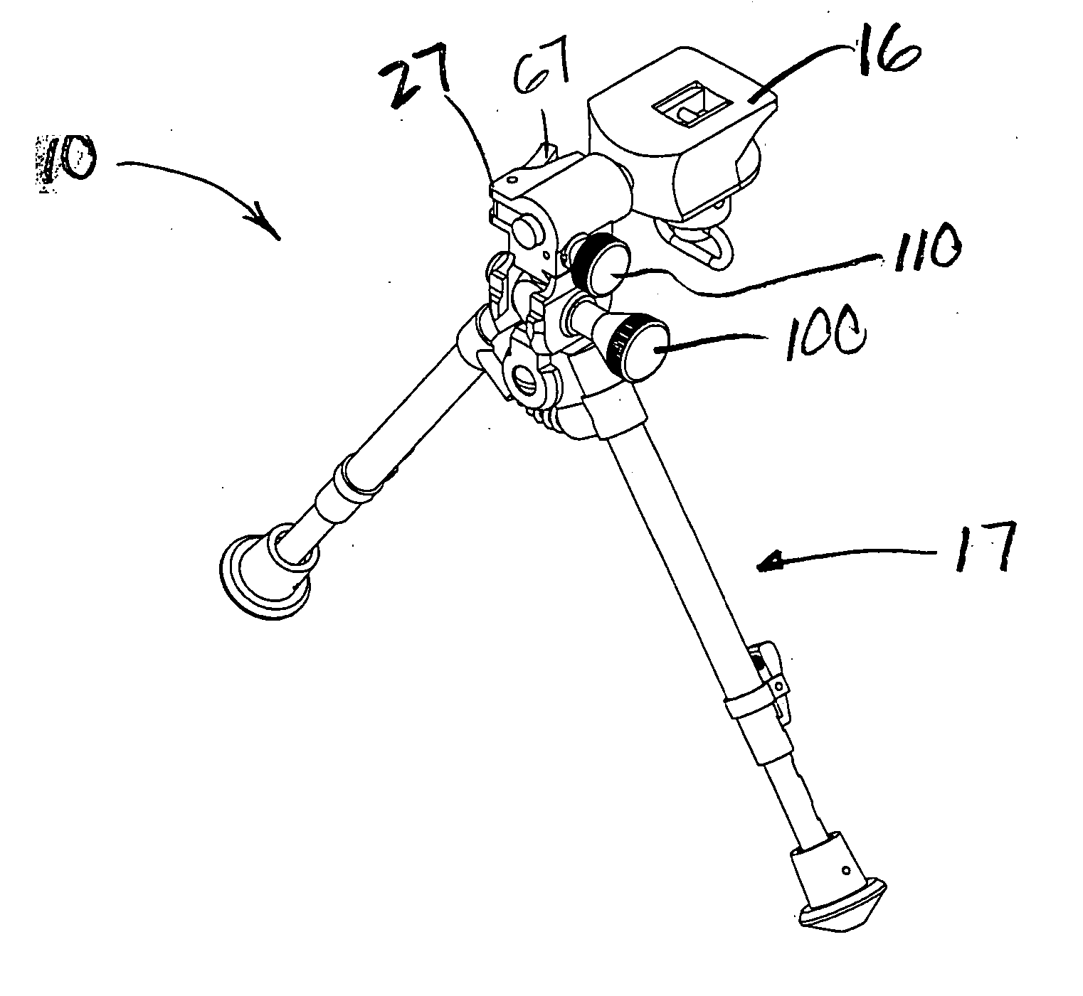
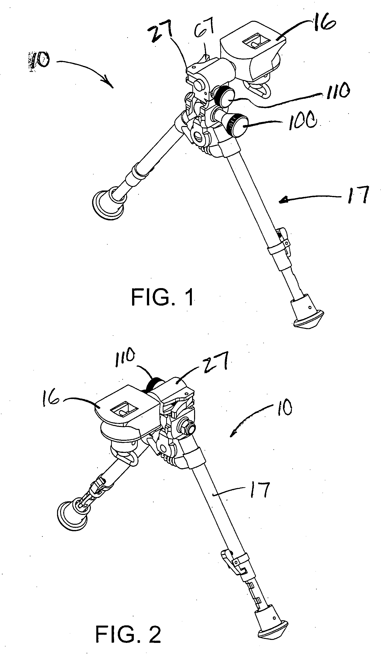
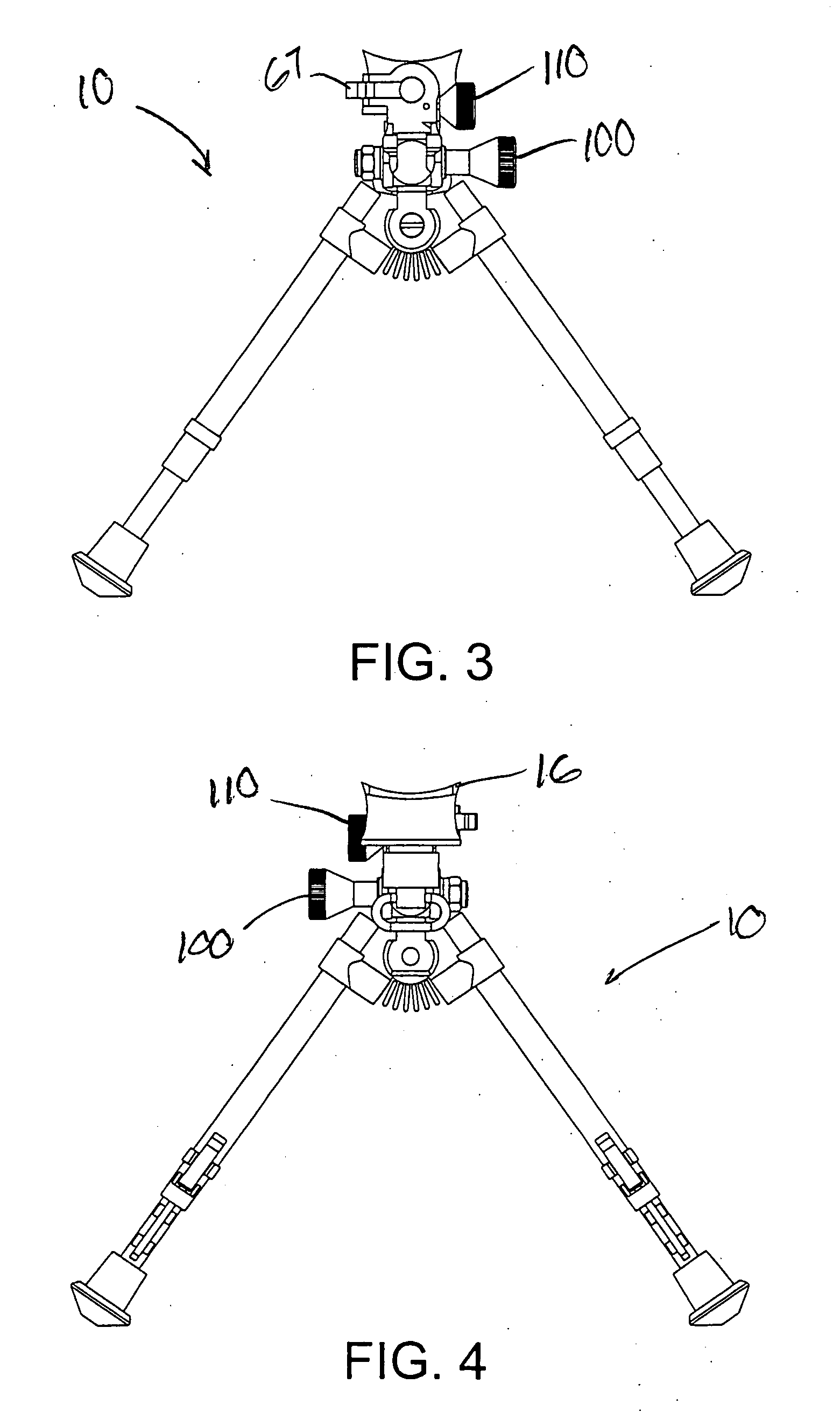
[0039] Referring now to FIGS. 1-15 in which like numerals indicate like parts throughout the several views, the present invention comprises a bipod mounting assembly for mounting a bipod 10 to a firearm such as a rifle (not shown). The bipod mounting assembly 10 generally is mounted to the forearm stock portion of a firearm.

[0040] Bipod mounting frame 17 has first and second extendable legs as described in co-owned U.S. Pat. Nos. 5,711,103 and 5,815,974, the entire disclosures of which are incorporated herein by reference.

[0041] The mounting block 16 generally is a substantially rectangularly-shaped block typically formed from plastic, fiber-filled resin or similarly durable, weather resistant materials. The mounting block 16 preferably includes a curved, concave upper surface 18, front surface 19, substantially flat bottom surface 21, concave side surfaces 22 and a curved, contoured rear surface 23. As illustrated in FIGS. 1-11 , rear surface 23 the mounting block 16 curves inwar...


PUM


Abstract

A bipod mounting device for mounting a bipod support to a forearm stock of a firearm or other bipod mounted device permits a user or shooter to selectively allow panning (or altering the aim point along an azimuth), tilting (or altering the orientation of a device relative to a horizontal line) and canting (or orienting a device at a selected rotational orientation relative to an axis of rotation). The bipod includes lockable controls for selectively limiting panning, tilting and canting in a manner which lets the shooter or user easily respond to changing situations when in the field.

Description

RELATED PATENT AND PENDING PATENT APPLICATION INFORMATION [0001] This application claims priority to provisional patent application No. 60 / 543,573, filed Feb. 12, 2004, the entire disclosure of which is incorporated herein by reference. This application is owned by the applicant / owner of U.S. Pat. Nos. 5,711,103 and 5,815,974, the entire disclosures of which are incorporated herein by reference. Additionally, this application is owned by the applicant / owner of provisional application No. 60 / 338,153, filed Nov. 13th, 2001, the entire disclosure of which is also incorporated herein by reference.BACKGROUND OF THE INVENTION [0002] 1. Field of the Invention [0003] The present invention relates to firearm accessories and support devices such as bipods, and more particularly, relates to an assembly for attaching a bipod support to the forearm stock of a firearm. The bipod and mount assembly enables quick attachment and detachment of the bipod to the firearm without modification of the fore...

Claims


Application Information

Patent Timeline
Patent Type & Authority Applications(United States)
IPC IPC(8): F16M11/12F16M11/24F16M13/00F41A9/62F41A23/10F41A31/00
CPCF16M11/10F16M11/12F16M11/2064F41A23/10F16M11/26F16M2200/044F16M2200/048F16M11/24
Inventor KENG, DAMATUSZCZAK, MACIEJ W.
Owner KENG
Why Eureka
Try Eureka