
Eureka
For R&D, Eureka makes reading and utilizing patents & technical documents easy.
Eureka AIR
Designed for self-driven R&D workflows. Generate viable solutions, solve complex R&D challenges, empower your innovation with AI.

Eureka Materials
Designed for material experts only. Revolutionize your material R&D, from search, analyze, to developing new materials.

TechResearch
Generate reliable direction feasibility study reports for your R&D in just a few steps.

TechSeek
Discover and master advanced knowledge NOW. Basics, ideas, possibilities, all at once.

TechMind
As an expert in R&D Theories, TechMind can generates customized viable solutions instantly.

TechRisk
Analyze your overall solution with one click, know your potential R&D risks in advance.

TechMonitor
Get weekly tech updates, stay abreast of the latest tech innovations and key insights.
Alternating current generator
- Summary
- Abstract
- Description
- Claims
- Application Information
AI Technical Summary
Benefits of technology
Problems solved by technology
Method used
Image

Examples
first embodiment
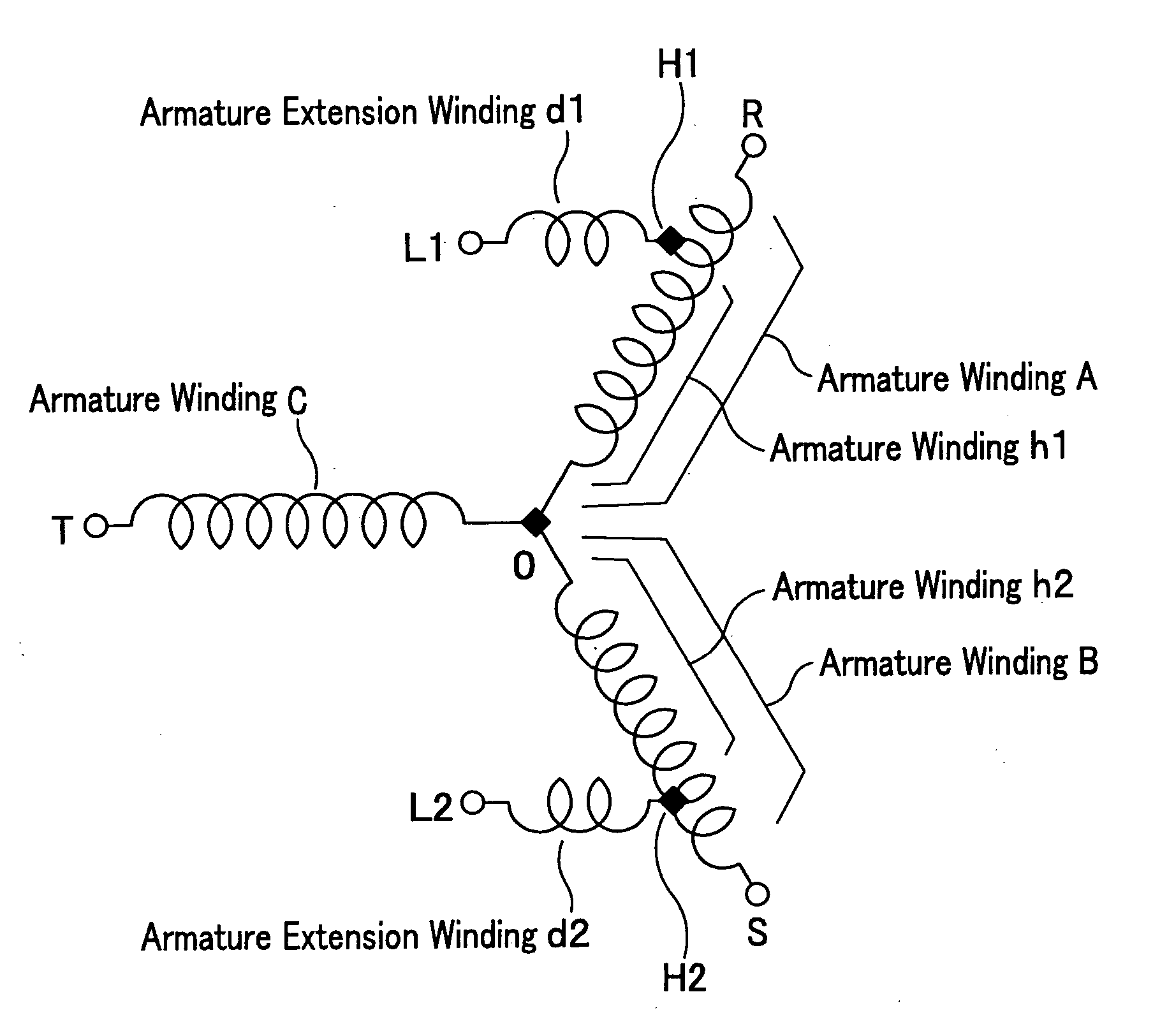
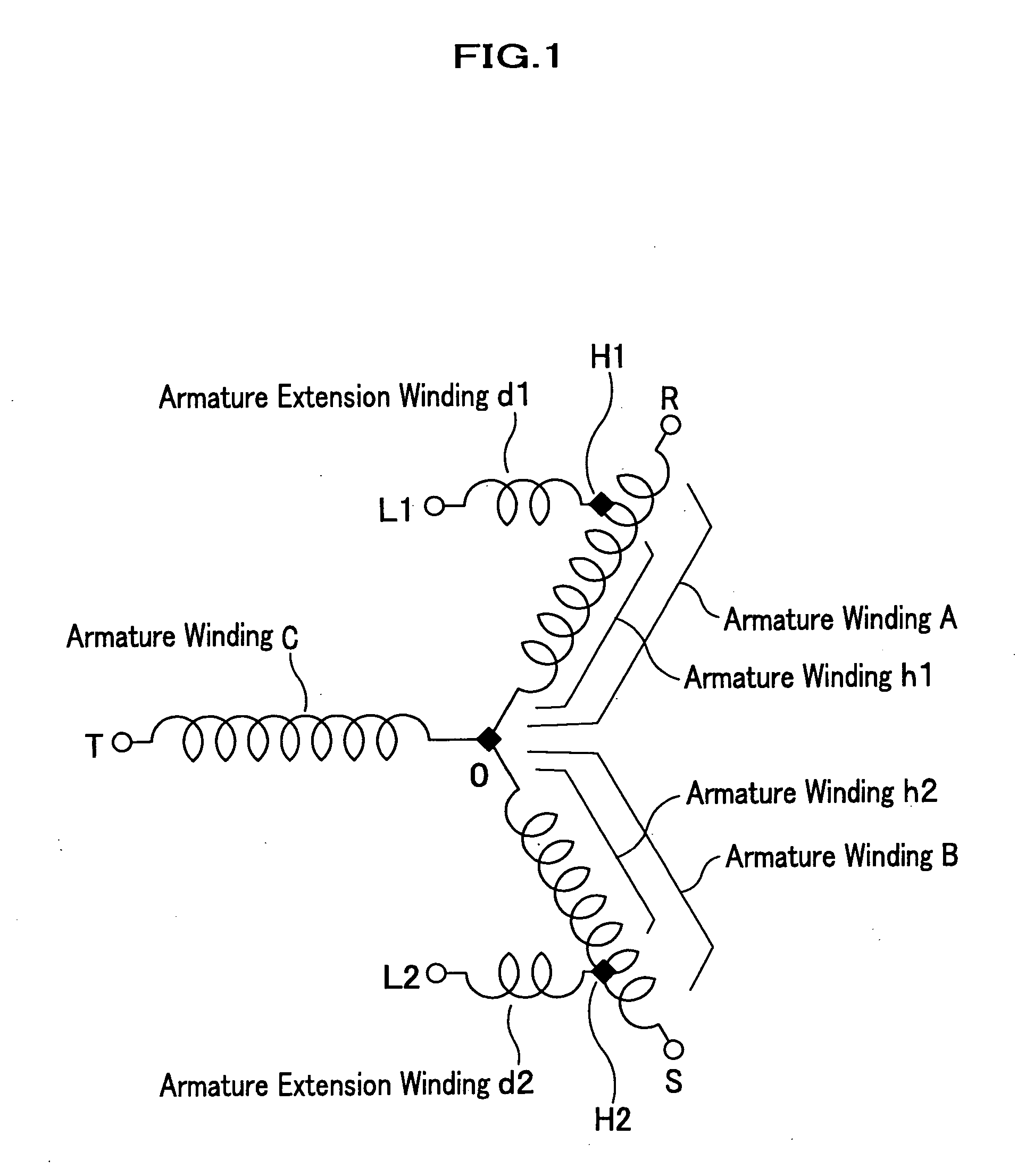
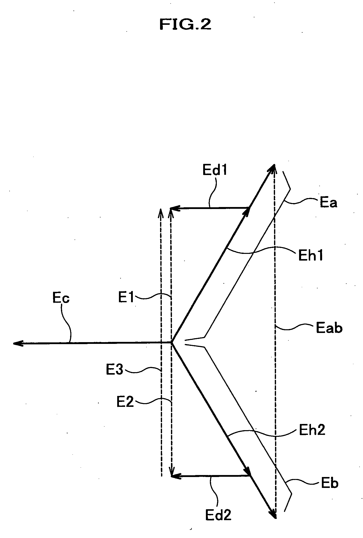
[0032]FIG. 1 is a circuit diagram of an alternating current generator according to the present invention, and FIG. 2 is a vector diagram showing a relationship of voltages generated in each of the armature windings when the alternating current generator of FIG. 1 is driven.
[0033] The alternating current generator of FIG. 1 has three armature windings A, B, and C, which are wound from a winding start end connected to a neutral point O to winding finish ends with the same winding numbers, and a stator that is connected to the neutral point O in Y-connection at a phase difference of 120 degrees (electric angle), respectively, and configures a three-phase power source. A grounding wire Le is connected to the neutral point O, as needed.
[0034] The alternating current generator comprises taps H1 and H2 provided at predetermined positions (in FIG. 1 intermediate points that are near the winding finish ends of the armature windings A and B, and where winding numbers of the armature windings...
second embodiment
[0039]FIG. 3 is a circuit diagram of an alternating current generator according to the present invention. FIG. 4 is a vector diagram showing a relationship of voltages generated in each of the armature windings when the alternating current generator of FIG. 3 is driven.
[0040] The alternating current generator of FIG. 3 is characterized in that a predetermined position of the tap H1 is the same as that of the terminal R. When setting the magnitude of the voltage vector Eab of FIG. 4 to be 200 V, a three-phase alternating current electric power of 200 V each is output from the terminals R, S, and T of FIG. 3; simultaneously a single-phase alternating current electric power of 100V each is output from between the terminal L1 and the neutral point O, and between the terminal L2 and the neutral point O; and a single-phase alternating current electric power of 200V is output from between the terminals L1 and L2.
third embodiment
[0041]FIG. 5 is a circuit diagram of an alternating current generator according to the present invention. This is characterized in that each MCCB (Moulded-Case Circuit Breaker) for an overcurrent protection is intervened between each of the terminals R, S, and T, and the relevant one of the armature windings A, B, and C. The MCCB is a breaker for shutting off a circuit of an electric power passage, and the voltage vectors shown in FIGS. 2 and 4 do not have any influence with respect to a presence or absence thereof. Accordingly, the MCCB can be provided at requested places within a range of conventional known technology.
[0042] This situation is the same in the embodiments described below.
PUM
 Abstract
Description
Claims
Application Information
 - R&D Engineer
- R&D Manager
- IP Professional
- Industry Leading Data Capabilities
- Powerful AI technology
- Patent DNA Extraction
Browse by: Latest US Patents, China's latest patents, Technical Efficacy Thesaurus, Application Domain, Technology Topic, Popular Technical Reports.
© 2024 PatSnap. All rights reserved.Legal|Privacy policy|Modern Slavery Act Transparency Statement|Sitemap|About US| Contact US: help@patsnap.com