Method and apparatus for improved position, velocity, orientation or angular rate sensor

a technology of angular rate and position, applied in the field of navigation systems, can solve problems such as preventing calibration

Inactive Publication Date: 2005-11-03
NOVARIANT
View PDF14 Cites 48 Cited by
  • Summary
  • Abstract
  • Description
  • Claims
  • Application Information

AI Technical Summary

Benefits of technology

[0016] A global navigation satellite system (GNSS) receiver system according to an embodiment of the present invention includes a processing unit; and one or more antenna units for receiving GNSS signals, each of the antenna units having a phase center; one or more inertial sensor units each positioned substantially adjacent said phase centers; and at least one communication channel between each antenna unit and said processing unit. In certain embodiments, the processing unit uses data from the one or more antenna units and data from the one or more inertial sensor units to determine at least one of a position, velocity, orientation, or angular rate of the object. In certai

Problems solved by technology

However, in situations where the tracking of the GNSS signals is compromised by low SNR, extreme antenna acceleration, destructive multipath or similar interference, latency between the IMU processor and the GNSS processor will generally preclude calibrating in the reverse direction.
However, such a topology also suffers from disadvantages related to the fact that the point

Method used


Image

  • Method and apparatus for improved position, velocity, orientation or angular rate sensor
  • Method and apparatus for improved position, velocity, orientation or angular rate sensor
  • Method and apparatus for improved position, velocity, orientation or angular rate sensor

Examples


Embodiment Construction

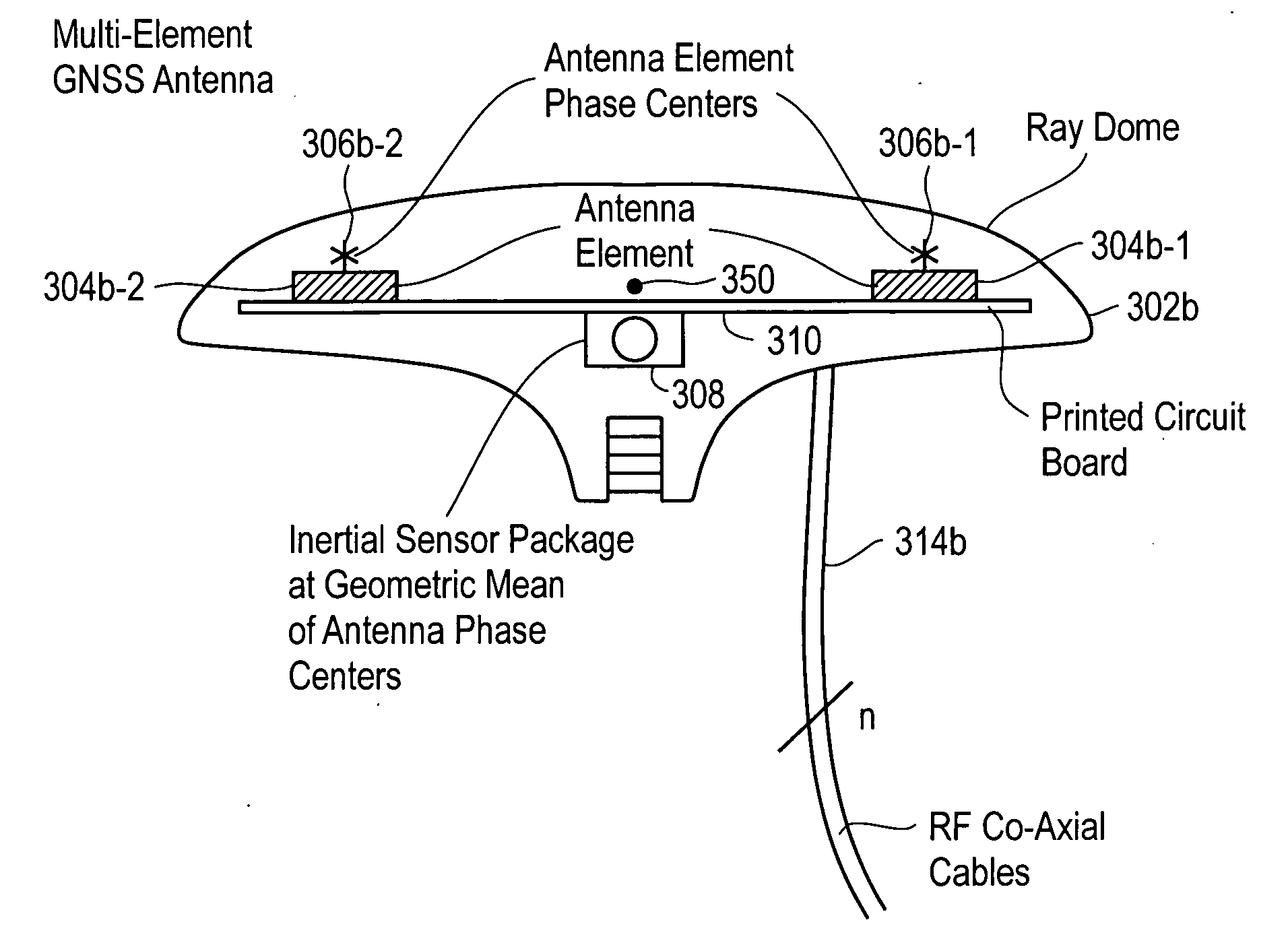
[0027] Turning now to FIG. 2A a block diagram of an exemplary navigation-positioning system 201 in accordance with an embodiment of the present invention is shown. In particular, the system provides global navigation satellite system (GNSS) based and inertial-based determination of vehicle position, velocity, orientation (attitude) and angular rate. Inertial sensors are co-located with GNSS antennas to more accurately derive the desired position and rate information.

[0028] It is noted that, while in exemplary embodiments, the GNSS receives positioning signals from the Global Positioning System (GPS), the system may be used with other radio based positioning or navigation systems, such as the GLONASS system, Galileo, or other systems such as pseudolites, low earth orbiting satellites (LEO), geosynchronous satellites, etc.

[0029] In the embodiment illustrated, the navigation-positioning system 201 includes a plurality of antenna units embodied as integrated GNSS Antenna-Inertial Sens...


PUM


Abstract

A global navigation satellite system (GNSS) receiver system includes a processing unit; and one or more antenna units for receiving GNSS signals, each of the antenna units having a phase center; one or more inertial sensor units each positioned substantially adjacent said phase centers; and at least one communication channel between each antenna unit and said processing unit.

Description

BACKGROUND OF THE INVENTION [0001] 1. Field of the Invention [0002] The present invention is directed generally to navigation systems and, particularly, to an improved system and method for position, velocity, orientation or angular rate sensing. [0003] 2. Description of the Related Art [0004] Global navigation satellite system (GNSS) sensors are used in vehicles such as aircraft to determine vehicle position, velocity, orientation (attitude), and angular rate. [0005] Use of GNSS position sensors to determine vehicle position is well known. GNSS position sensors can also be used to determine a velocity estimate by solving a set of range-rate equations or by smoothing (curve fitting) a set of position measurements. [0006] A GNSS position sensor typically includes an antenna and an RF coaxial cable coupling the antenna to a GNSS signal processing unit. The GNSS antenna generally includes an antenna element and associated filtering and amplification electronics. Position is sensed at t...

Claims


Application Information

Patent Timeline
IPC IPC(8): G01S19/14G01S5/02G01S5/14G01S19/53
CPCG01S19/15G01S19/35G01S19/47G01S19/39G01S19/36G01S19/396
Inventor MONTGOMERY, PAUL YALDENLAWRENCE, DAVID GARY
Owner NOVARIANT
Why Eureka
Try Eureka