Endoscope apparatus

Inactive Publication Date: 2005-11-03
OLYMPUS CORP
View PDF4 Cites 36 Cited by
  • Summary
  • Abstract
  • Description
  • Claims
  • Application Information

AI Technical Summary

Benefits of technology

[0008] In view of the forgoing, it is an object of the present invention to provide an endoscope apparatus, which can correct length of a signal line wi

Problems solved by technology

However, if said signal line is long, it causes delay during the drive signal and/or the imaging signal are transmitted through said signal line.
Thus, within said video processor, the timing of the imaging signal received in timing with sendi

Method used


Image

  • Endoscope apparatus
  • Endoscope apparatus
  • Endoscope apparatus

Examples


Embodiment Construction

[0028] Embodiments of the present invention will be described below with reference to the drawings.

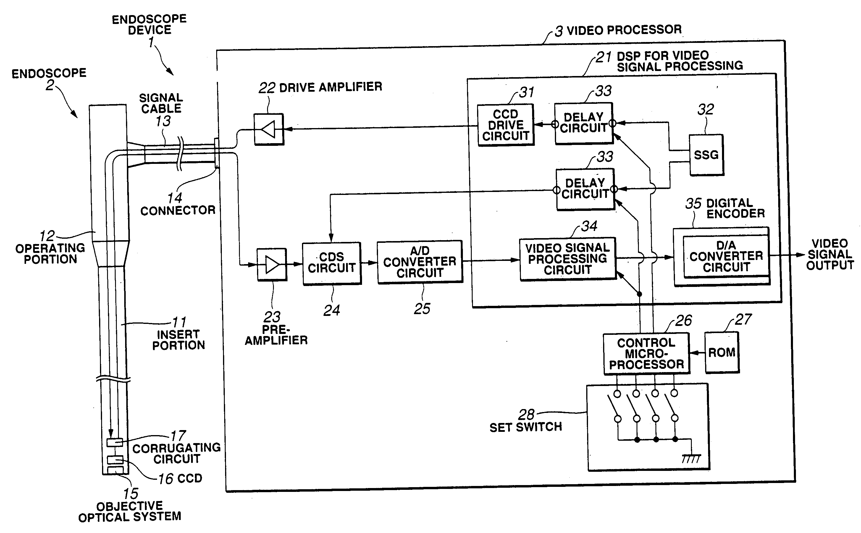
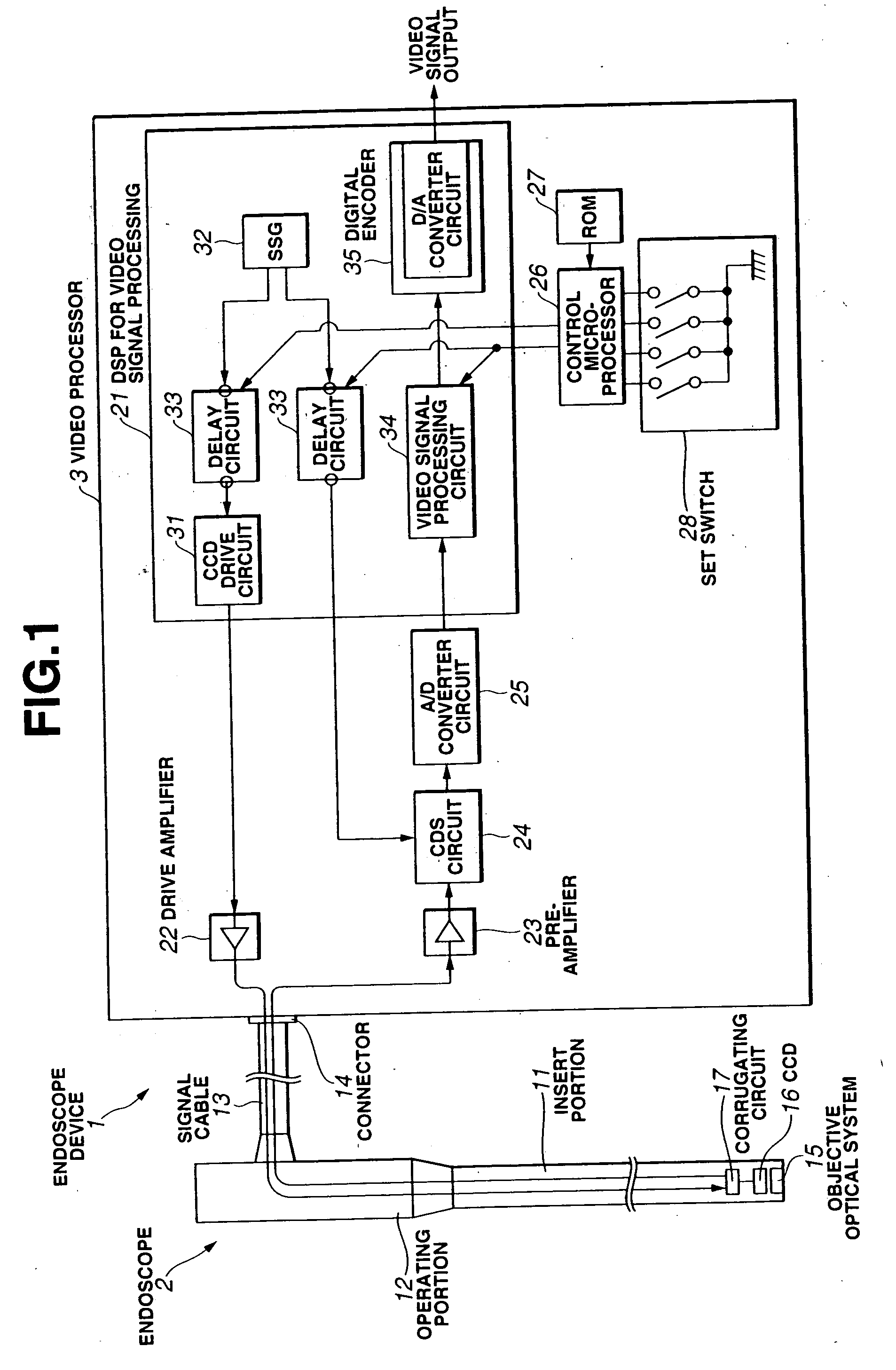
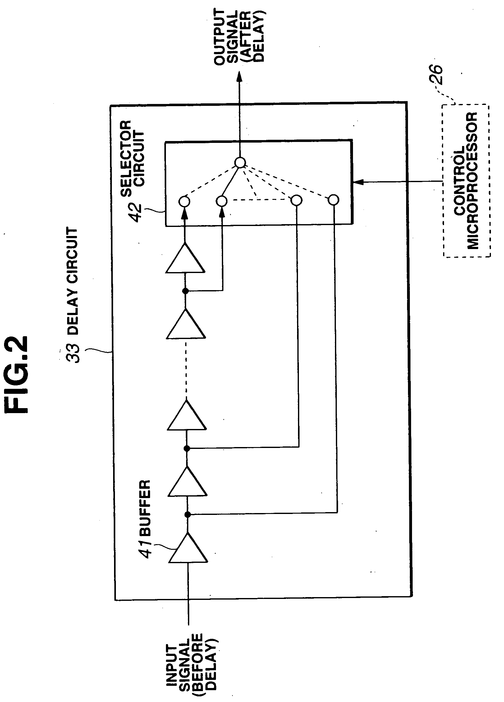
[0029]FIG. 1 and FIG. 2 relate to a first embodiment of the present invention. FIG. 1 is a block diagram showing a whole configuration of an endoscope apparatus, and FIG. 2 is a block diagram showing a configuration of a delay circuit.

[0030] As shown in FIG. 1, an endoscope apparatus 1 of this embodiment is composed of an endoscope 2, which is inserted to within a body cavity or within a duct in an equipment (duct in the followings), etc. to obtain an imaging signal which corresponds to an object image, and a video processor 3, which generates a video signal which can be displayed on a monitor from the imaging signal obtained in the endoscope 2.

[0031] Said endoscope 2 is composed of a long, narrow insert portion 11 for inserting to within a body cavity, within a duct, or the like, an operating portion 12 attached in line on the base end side of the insert portion 11 for holding and ...


PUM


Abstract

A drive signal from an SSG drives a CCD through a delay circuit and the like. An imaging signal from the CCD is converted to a video signal in a CDS circuit, which is driven by a sample hold signal given through the delay circuit, and is converted to a video signal that can be displayed on a monitor through an A/D converter circuit, a video signal processing circuit and a digital encoder to be output. Here, by correcting phases of the imaging signal and the sample hold signal, length of a signal line is corrected. Also, since the delay circuit is constructed by being incorporated in a DSP for video signal processing, which includes a video signal processing circuit and the like, the construction is simplified. Thus, the number of parts is reduced, and it can be constructed inexpensively.

Description

BACKGROUND OF THE INVENTION [0001] 1. Field of the Invention [0002] The present invention relates to an endoscope apparatus, which is provided at a pointed end portion of an endoscope insert portion or whose a signal line is connected to an imaging element removably attached to an eyepiece portion in the endoscope. [0003] 2. Description of the Related Art [0004] Recently, an endoscope is widely used whose long, narrow insert portion is inserted to within a body cavity, a duct, or the like to observe an object within the body cavity, the duct, or the like. Such an endoscope, for example, includes a CCD as an imaging means for imaging an object image at the pointed end of the insert portion. A signal line extended from the CCD is inserted through within an operating portion, which is mounted in line within the insert portion or on the side of a insert portion base end. The signal line is extended from the operating portion to be electrically connected to an external video processor. T...

Claims


Application Information

Patent Timeline
IPC IPC(8): A61B1/04H04N7/18G02B23/24
CPCH04N7/183
Inventor ONO, MITSUNOBUMURATA, MASANAO
Owner OLYMPUS CORP
Why Eureka
Try Eureka