Method and system for determining user location in a wireless communication network

a wireless communication network and user technology, applied in the field of user location determination, can solve the problems of inaccurate estimation of the time of arrival or angle of arrival, inability to use a gps system indoors, and inability to see the gps satellite, so as to maximize the probability, accurate determination of the user location, and the effect of greater accuracy

Inactive Publication Date: 2005-11-03
UNIV OF MARYLAND
View PDF3 Cites 99 Cited by
  • Summary
  • Abstract
  • Description
  • Claims
  • Application Information

AI Technical Summary

Benefits of technology

[0016] To overcome the shortcomings of the prior art and to provide user location determination with greater accuracy, the present invention provides a method for locating a computing device adapted to a wireless communication network relative to locations of a plurality of access points within the network. The method of the present invention is carried out by first establishing a plurality of discrete-space radio maps having coordinates corresponding to locations in space at which a calibration signal strength is measured. The coordinates of each of the discrete-space radio maps have a probability distribution of calibration signal strength from a corresponding one of the access points stored thereat. Once the discrete-space radio maps have be

Problems solved by technology

However, the line-of-sight to GPS satellites is unavailable inside buildings and hence the GPS system cannot be used indoors.
While these systems are promising in outdoor environments, their effectiveness in indoor environments is limited by the multiple reflections suffered by the electromagnetic radiation, which leads to an inaccurate estimate of the time of arrival or angle of arrival.
However, if the walls of a room block the IR signal, the user cannot be accurately located within the blocked area.
IR based location techniques also suffer from limited range, poor performance in the presence of direct sunlight, and significant installation and maintenance costs.
Such systems suffer from steep

Method used


Image

  • Method and system for determining user location in a wireless communication network
  • Method and system for determining user location in a wireless communication network
  • Method and system for determining user location in a wireless communication network

Examples


Embodiment Construction

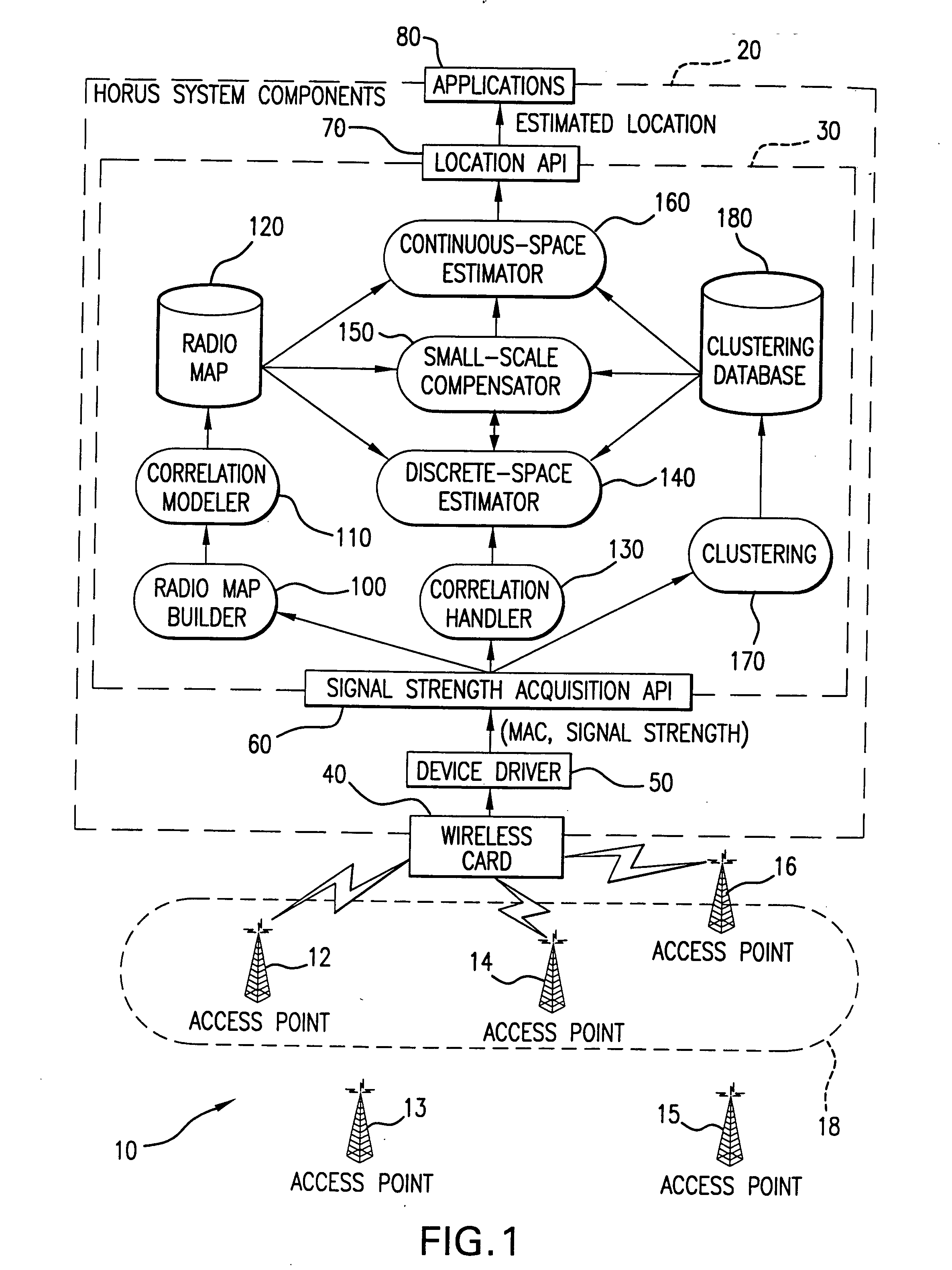
[0027] Referring to FIG. 1, system components of the present invention, designated “Horus” by the inventors thereof, are shown as implemented in a wireless communication network specified by the IEEE Standard 802.11. The 802.11 wireless network has all of the elements to implement the invention and is used herein to exemplify the invention without limiting the scope thereof. A wireless local area network (WLAN) implemented in accordance with IEEE 802.11 Standard, generally indicated at 10, consists of a plurality of access points 12-16 and a computing device 20. Although WLAN 10 is shown in FIG. 1 with only five access points and one computing device, a typical implementation includes many more of both access points and computing devices. Briefly stated, the present invention acquires an indication of the signal strength of a set of access points 18 and, via a previously constructed radio map, as will be fully described below, locates the receiving computing device 20 as being at a ...


PUM


Abstract

In a wireless communication network, the location of an addressable receiver relative to the locations of a plurality of addressable sources of electromagnetic radiation is found using probabilistic models of the signal strength measured at the addressable receiver. The inventive method provides location determination on a finer spatial scale than was heretofore available. A region of interest is calibrated via a discrete-space radio map storing probability distributions of received signal strength at the measurement locations. The stored probability distributions are compensated for temporal variability and biases, such as through temporal correlations of the sampled received signal strength. A measurement of the signal strength at the addressable receiver from each of the plurality of addressable sources is used in conjunction with the discrete-space radio map to identify one of the coordinates thereof that maximizes the conditional probability P(x|s), where x is the radio map location and s is a vector of measured signal strengths. Small spatial scale variability can be compensated for using a perturbation technique. The method further implements a continuous-space estimator to return an estimated user location that falls between discrete-space radio map locations.

Description

BACKGROUND OF THE INVENTION [0001] 1. Field of the Invention [0002] The invention described herein is related to user location determination via the reception of electromagnetic signals. More specifically, the invention is related to determining the location of an addressable receiver in a wireless communication network, such as an IEEE 802.11 compliant wireless local area network. [0003] 2. Description of the Prior Art [0004] Recent trends in wireless communication, computer networking, and information dispersal have given rise to the field of ubiquitous or pervasive computing. Ubiquitous computing allows the use of a plurality of computing devices positioned throughout a physical environment, but the access to a particular computer is essentially invisible to the user. Ideally, a person would continually interact with hundreds of nearby wirelessly interconnected computers. A user would be able to access the computer network, or rather the computer network could access the user, vi...

Claims


Application Information

Patent Timeline
IPC IPC(8): G01S19/46G01S19/09H04B17/40H04L12/28H04L12/56H04L27/00H04L27/26H04W64/00
CPCH04L27/2601H04B17/318H04W64/00H04W24/00
Inventor AGRAWALA, ASHOK K.YOUSSEF, MOUSTAFA
Owner UNIV OF MARYLAND
Why Eureka
Try Eureka